
Inspection
- Make
- Aston Martin
- Model
- DB9 Factory Workshop Manual
- Year
- Issue 2, 2005
- Section
- Body Ventilation system › Inspection
12 Climate controlInspection
Inspection
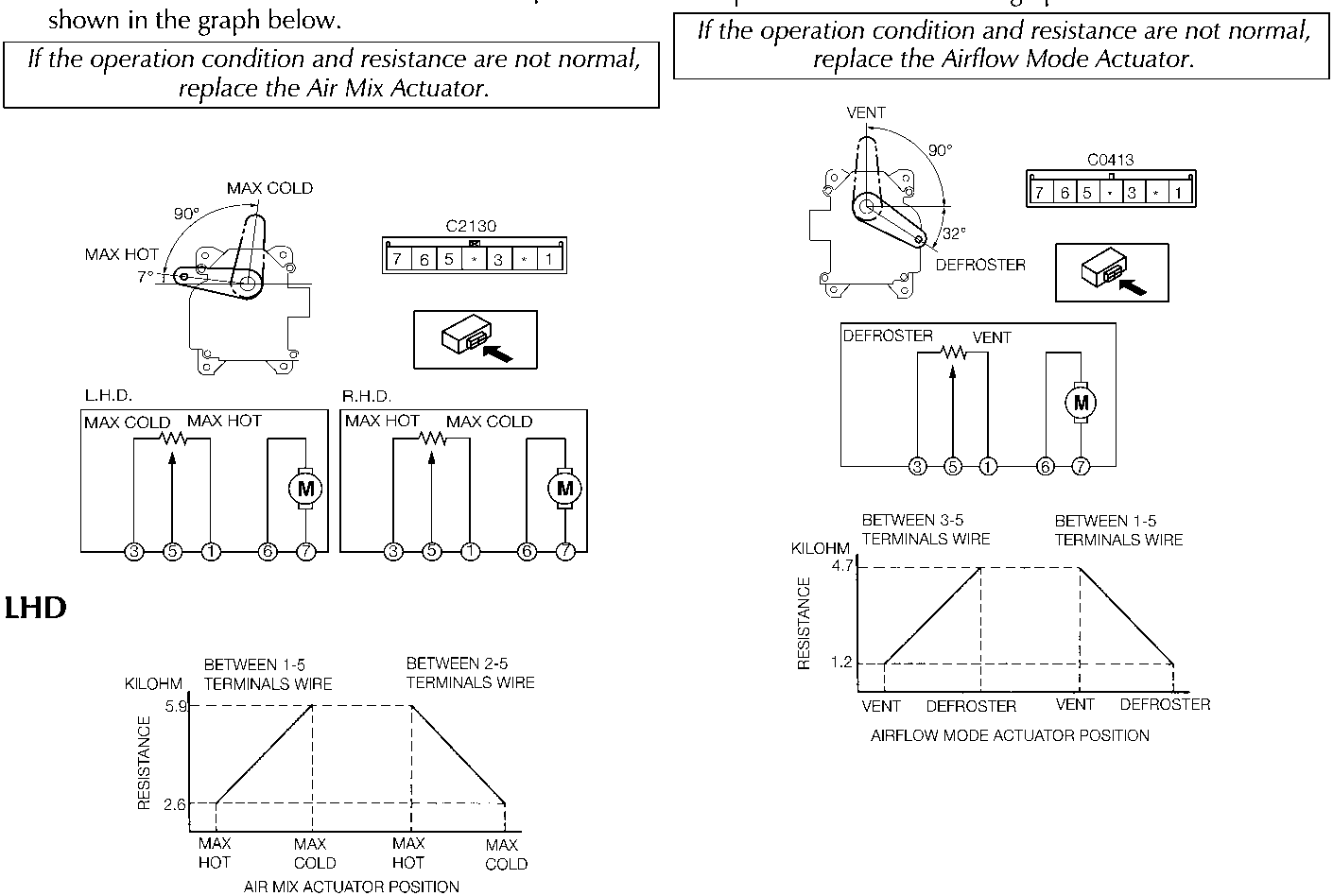
- Connect the battery positive voltage to Air Mix Actuator terminal 6 (or 7), and ground to terminal 7 (or 6). Verify that the Air Mix Actuator operates as shown.
If the operation condition is not normal, replace the Air Mix Actuator.
| Terminal (C2130) | Air Intake Actuator Operation | |
|---|---|---|
| 1 | 3 | Cold - Hot (LHD) Hot - Cold (RHD) |
| B+ | Ground | |
| Ground | B+ | Hot - Cold (LHD) Cold - Hot (RHD) |
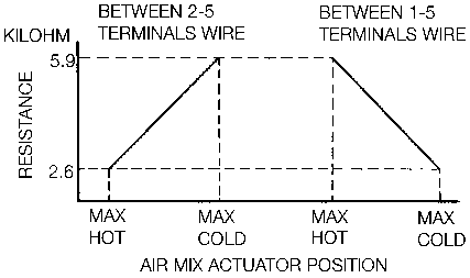
- Check that the resistance between terminals 3 and 5, and 1 and 5 matches the Air Mix Actuator operation as shown in the graph below.
If the operation condition and resistance are not normal, replace the Air Mix Actuator.
RHD
Airflow Mode Actuator
Inspection
- Connect the battery positive voltage to the Airflow Mode Actuator terminal 6 (or 7), and ground to terminal 7 (or 6). Verify that the Airflow Mode Actuator operates as shown.
If the operation condition is not normal, replace the Airflow Mode Actuator.
| Terminal | Airflow Mode Actuator operation | |
|---|---|---|
| 6 | 7 | Defroster - Vent |
| B+ | Ground | |
| Ground | B+ | Vent - Defroster |
- Verify that the resistance between terminals 1 and 5, and 3 and 5 matches the Airflow Mode Actuator operation as shown in the graph below.
If the operation condition and resistance are not normal, replace the Airflow Mode Actuator.
Parts & tools for this job For 2005 Aston Martin DB9
- TOOLTrim removal tool kitSearch: trim removal tool kit
- PARTTouch-up paintSearch: Aston Martin touch up paint
- PARTPanel clip assortmentSearch: Aston Martin panel clips assortment
Links open Amazon search results in a new tab. As an Amazon Associate I earn from qualifying purchases.