| –
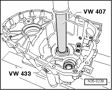
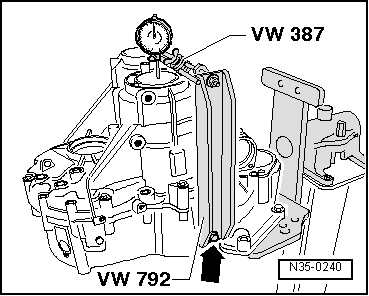
| Set up measuring tools and secure with bolt -arrow- to clutch housing. |
| –
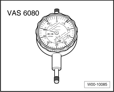
| Set dial gauge -VAS 6080- (3 mm measuring range) to “0” with 1 mm preload. |
| –
| Loosen clutch housing/gearbox housing securing bolts diagonally until output shaft is free to move in gearbox housing. |
| –
| Read off play on gauge and note reading (example: 0.14 mm). |

Note | If no play is indicated on the dial gauge when the clutch housing/gearbox housing securing bolts are loosened, fit a 1.95 mm shim (part number -084 409 383 AS-), or if necessary a 2.20 mm shim (part number -084 409 383 BD-) for performing the measurement. |
| Determining thickness of shim |
| The specified bearing preload is attained by subtracting the measured value (0.14 mm) from the inserted shim (1.70 mm) and adding a constant value for preload (0.20 mm). |
|
|
|