audi Workshop Repair Guides

Audi Workshop Service and Repair Manuals

Removing and installing mounting bracket (vehicles with automatic gearbox) > < Removing and installing mounting for brake servo push rod
Removing and installing mounting bracket (vehicles with manual gearbox)
Special tools and workshop equipment required
t  Torque wrench -V.A.G 1331-
t  Reversible ratchet -V.A.S 5122-
t  Release tool -T40168- for brake light sensor.
   
t  Release tool -T40136-
Removing
  WARNING
Line the footwell with a sufficient number of cloths to protect against brake fluid escaping at the clutch pedal.
  A46-10132
–  Remove dash panel trim on driver's side -1 ... 3-.
  A68-10158
–  Unplug electrical connector on footwell vent -C-.
–  Remove footwell vent -A-B-.
–  Remove brake light sensor → Chapter.
–  Unplug electrical connector from accelerator pedal module.
–  Separate brake pedal from brake servo → Chapter.
  WARNING
If possible, stop on brake pedal should always be left installed; otherwise mounting for brake light sensor could break off if brake pedal is released too abruptly.
  A87-10491
–  Remove over-centre spring -2- on clutch pedal -1- → Rep. gr.30.
  Note
Note correct installation position of over-centre spring for subsequent re-installation.
  A30-10156
–  Pull pin -4- in clutch pedal for linkage to clutch master cylinder out of pedal arm.
  Note
Do not release catches -1 and 2- before removal.
–  Release clutch master cylinder using release tool -3355-.
Turn special tool clockwise -arrow-.
  A30-10160

–  Remove body brace.
–  Remove plenum chamber partition panel → Rep. gr.50.
–  Remove cover -2- above brake fluid reservoir.
   

The cover -2- is not fitted on all vehicles.
   
–  Remove bolts -1- securing brake servo to mounting bracket.
  A47-0186
–  Remove nuts -16- on mounting bracket guides.

–  Use full range of steering column adjustment to move steering wheel out as far as possible towards driver's seat.
–  Turn steering wheel to straight ahead position. Wheels are in straight-ahead position.
  Note
Dash panel insert and steering wheel do not have to be removed in order to remove steering column.
   
–  Remove bolt -2- for steering column at bottom.
  A48-10179
–  Remove bottom bolts -2 to 4- for steering column and mounting bracket.
  A48-10182
–  Unclip trim cover -2- from top of trim -1- for steering column switch module (SMLS) -arrow A-.
–  Detach wiring guides from steering column.
  Note
Shown in illustration without steering wheel. Do not remove steering wheel and dash panel insert.
  A68-10160
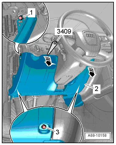
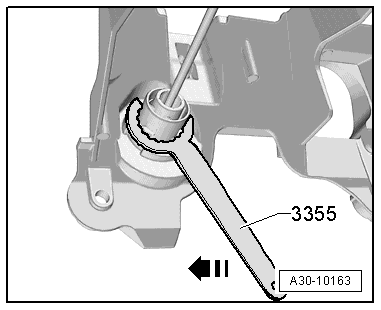
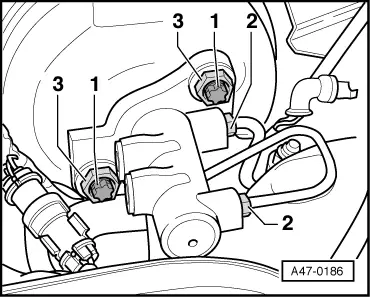
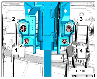
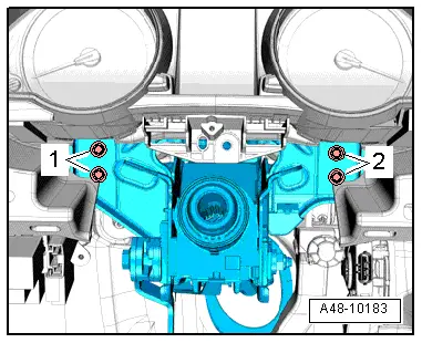
–  Unscrew bolts -1 and 2- for steering column from central tube, supporting steering column by hand from below.
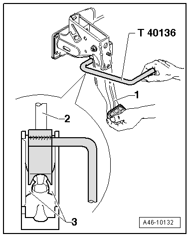
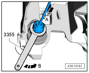
  Note
Use ratchet with 3/8" drive (commercially available) and multi-point bit with extension to slacken and remove bolts -1 and 2-.
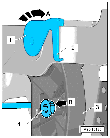
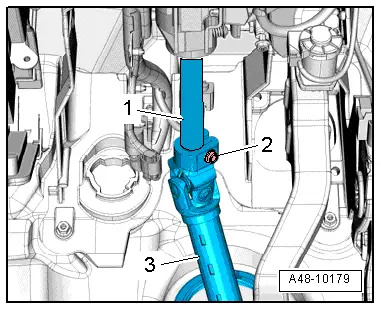
–  Pull out steering column from steering shaft
–  Carefully put down steering column with steering wheel.
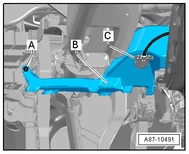
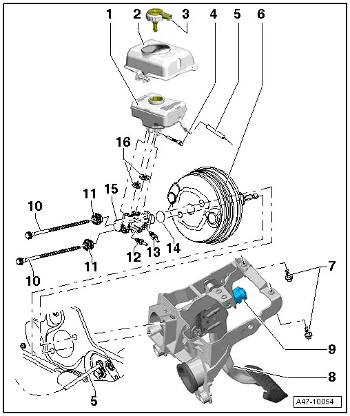
–  Remove mounting bracket from vehicle.
  Caution
Make sure that the clutch master cylinder is not disconnected from the hydraulic line when taking out the mounting bracket.
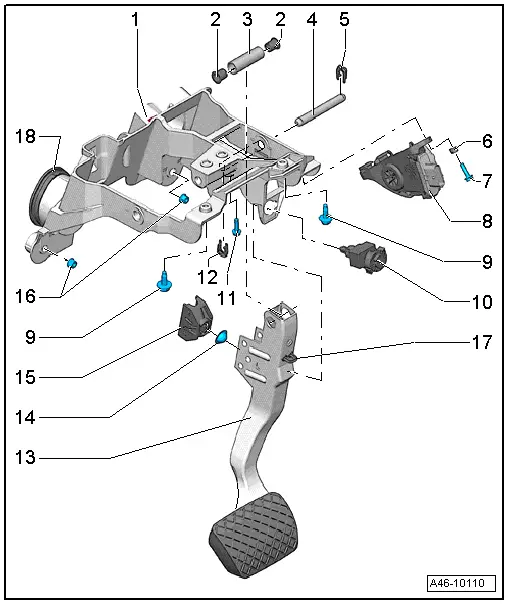
The clutch master cylinder remains in the vehicle.
Installing
  WARNING
If possible, stop on brake pedal should always be left installed; otherwise mounting for brake light sensor could break off if brake pedal is released too abruptly.
Check that the seal on the clutch master cylinder is correctly seated before fitting the mounting bracket.
–  Insert mounting bracket in guides on vehicle.
Guide clutch master cylinder through aperture in mounting bracket and turn mounting bracket slightly to right so that cylinder mounts can be guided through mounting bracket.
–  Fit nuts at mounting bracket guides to hold mounting bracket in position.
  A48-10183
–  Install and tighten bolts -1- securing brake servo to mounting bracket.
  Note
First install and tighten bolts securing brake servo to mounting bracket.
  A47-0186
–  Tighten nuts -16- at mounting bracket guides.

–  Secure clutch master cylinder in mounting bracket using release tool -3355-.
   
Turn special tool anti-clockwise -arrow B-, while at the same time pulling master cylinder forwards -arrow-.
  A30-10162
–  Push pin -4- for linkage to clutch master cylinder flush into clutch pedal.
Note correct installation position of pin. The shoulder -B- on the pin must be aligned with the slot in the pedal arm.
  A30-10160
–  Install over-centre spring -2- on clutch pedal → Rep. gr.30.
–  Plug in electrical connector for accelerator pedal module.
Attaching brake pedal to brake servo
–  Hold ball head of push rod in front of mounting and push brake pedal towards brake servo so that ball head audibly locks into place.
  WARNING
If possible, stop on brake pedal should always be left installed; otherwise mounting for brake light sensor could break off if brake pedal is released too abruptly.
–  Install brake light sensor → Chapter.
  A30-10156
–  Slide steering column -1- onto steering shaft -3-.
–  Fit steering column to central tube and insert bolts.
  Note
Note different lengths of bolts.
  A48-10179
–  Tighten bolts -1 and 2- to 20 Nm in diagonal sequence.
  Note
Use ratchet with 3/8" drive (commercially available) and multi-point bit with extension to fit bolts -1 and 2-.
–  Use torque wrench -V.A.G 1331- and reversible ratchet -V.A.S 5122- with extension to tighten bolts to 20 Nm.
–  Clip trim cover into top of trim for steering column switch module (SMLS).
–  Attach wiring guides to steering column.
  A48-10183
–  Tighten bolt on steering shaft -2- to 20 Nm.
  A48-10179
–  Fit bottom bolts -1 to 4- for steering column and mounting bracket and tighten to 20 Nm.
  A48-10182
–  Install footwell vent -A-B-.
–  Tighten bolt securing footwell vent -A-.
–  Attach electrical connector to footwell vent -C-.
  A87-10491
–  Install dash panel trim on driver's side -1 ... 3-.
–  Install cover -2- above brake fluid reservoir.
  A68-10158

The cover -2- is not fitted on all vehicles.
–  Install plenum chamber partition panel → Rep. gr.50.
–  Install body brace → Rep. gr.40.
   

Removing and installing mounting bracket (vehicles with automatic gearbox) > < Removing and installing mounting for brake servo push rod