
A5
|
 Note
Note
|
|
 Caution
|
|
|
|
Note
|
|
|
|
|
|
Note
|
|
Note
Note
|
|
|
|
|
|
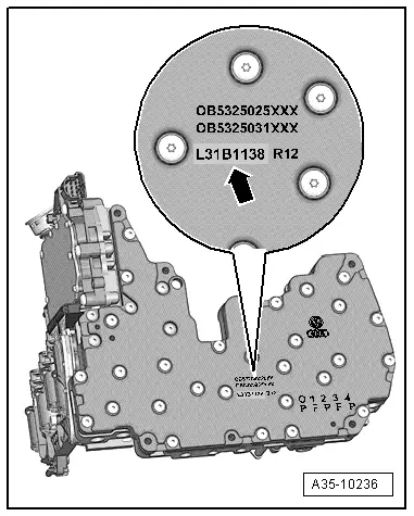
| Identification of mechatronic unit | Explanation: in this example „L31B1138“ | |||
| L | 31 | B1 | 138 | |
| L | Year of manufacture: L = 2010 K = 2009 J = 2008 ... etc. | |||
| 31 | Calendar week of year of manufacture | |||
| B1 | Manufacturer's code for day and shift no. Monday: shift 1 = A1, shift 2 = B1, shift 3 = C1 Tuesday: shift 1 = D1, shift 2 = E1, shift 3 = F1 Wednesday: shift 1 = G1, shift 2 = H1, shift 3 = I1 ... etc. | |||
| 138 | Serial number of unit per shift and day, in this case the 138th mechatronic unit in shift B1 | |||
Note
|
|
|
|
|
|
|
|
|