
Timing diagrams (page 3 of 3)
- Make
- Fiat
- Model
- Bravo /Brava (182) Factory Service Manual
- Year
- 1995–2001
- Section
- Engine (98 range)
00 Introduction and technical dataTiming diagrams · page 3 of 3
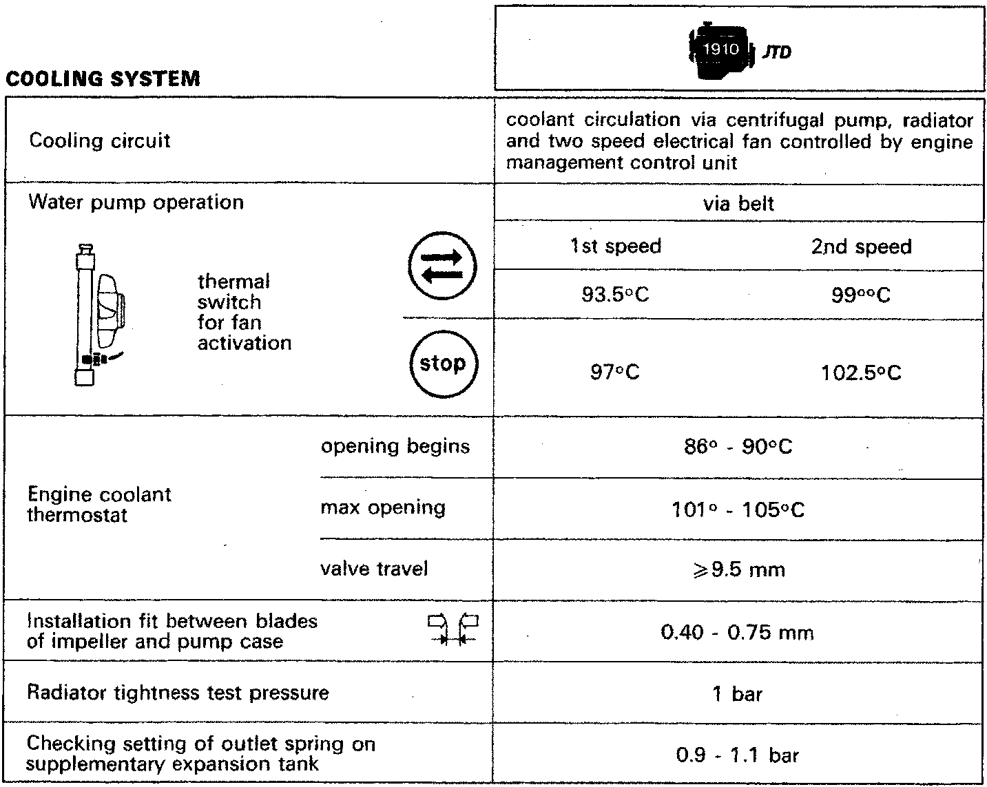
| Cooling circuit | coolant circulation via centrifugal pump, radiator and two speed electrical fan controlled by engine management control unit | ||
|---|---|---|---|
| Water pump operation thermal switch for fan activation |
via belt | ||
| 1st speed | 2nd speed | ||
| 93.5°C | 99°C | ||
| 97°C | 102.5°C | ||
| Engine coolant thermostat | opening begins | 86° - 90°C | |
| max opening | 101° - 105°C | ||
| valve travel | ≥9.5 mm | ||
| Installation fit between blades of impeller and pump case | 0.40 - 0.75 mm | ||
| Radiator tightness test pressure | 1 bar | ||
| Checking setting of outlet spring on supplementary expansion tank | 0.9 - 1.1 bar | ||
Parts & tools for this job For 1995 Fiat Bravo
- PARTEngine gasket setSearch: Fiat Bravo 1995 engine gasket set
- TOOLTorque wrenchSearch: 3/8 inch torque wrench
- TOOLFeeler gauge setSearch: feeler gauge set
Links open Amazon search results in a new tab. As an Amazon Associate I earn from qualifying purchases.