
Key
- Make
- Fiat
- Model
- Bravo /Brava (182) Factory Service Manual
- Year
- 1995–2001
- Section
- Description and operation (Automatic) › Key
21 Gearbox and differentialKey
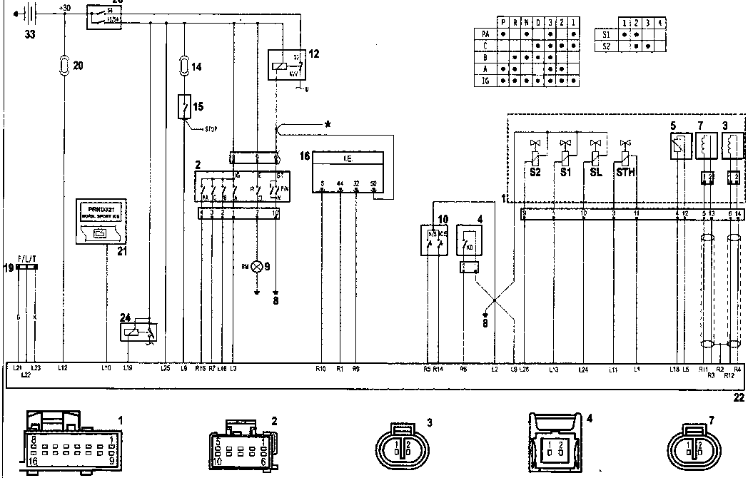
* To safety control unit
Key
- Solenoid assembly on automatic transmission
- Selector lever position sensor
- Vehicle speed sensor
- Kick-down switch
- Gearbox oil temperature sensor
- Main shaft rpm sensor
- Rear earth
- Reversing lights
- NORMAL/SPORT and ICE mode switches
- Starter motor relay
- 15A fuse protecting STOP lights
- STOP lights switch
- Fuel injection/ignition electronic control unit (P/N position signal)
- Automatic transmission safety electronic control unit
- Diagnostic socket for Fiat/Lancia tester
- 5A fuse 5A protecting control module
- Warning lights on instrument panel (for displaying selector lever position, selected driving mode and fault indication)
- Control module
- Ignition switch
- Gearbox oil cooling fan relay
- Battery
Wiring connectors (view of contact side)
Parts & tools for this job For 1995 Fiat Bravo
- TOOLTorque wrenchSearch: 3/8 inch torque wrench
- TOOLSocket setSearch: socket set metric
- BOOKHaynes manualSearch: Haynes manual Fiat Bravo
Links open Amazon search results in a new tab. As an Amazon Associate I earn from qualifying purchases.