
Lock-up control solenoid
- Make
- Fiat
- Model
- Bravo /Brava (182) Factory Service Manual
- Year
- 1995–2001
- Section
- Description and operation (Automatic) › Lock-up control solenoid
The recovery stragegy involves the deactivation of all the solenoids, so no automatic gear changes are ef-fected, the torque converter is not locked and the hydraulic pressure is not varied.
The vehicle can travel because each position of the selector lever corresponds to the engagement of a par-ticular transmission ratio, by the movement of the hydraulic distributor.
| Selector lever position | R | D | 3 | 2 | 1 |
|---|---|---|---|---|---|
| Gear engaged | Reverse | 4th | 4th | 3rd | 1st |
Lock-up control solenoid
In the case of error, the torque converter locking function is disabled.
Coolant temperature sensor
In the case of error, a substitutive value of 75°C is assigned.
Kick-down switch
In the case of error, it is considered ON if the throttle valve aperture is greater than 73.5%, OFF if it less than 70%.
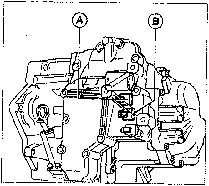
GEAR CHANGE SOLENOIDS
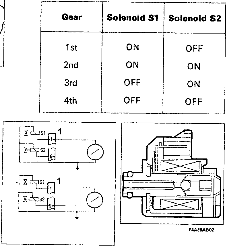
The gear change solenoids S1 (A) and S2 (B) are located at the front of the gearbox and they manage the gear changes. The solenoids are actually normally closed (N.C.) electrovalves which, receiving a signal from the control module, change their position to allow the engagement of the different trans-mission ratios, in accordance with the fol-lowing table.
| Gear | Solenoid S1 | Solenoid S2 |
|---|---|---|
| 1st | ON | OFF |
| 2nd | ON | ON |
| 3rd | OFF | ON |
| 4th | OFF | OFF |
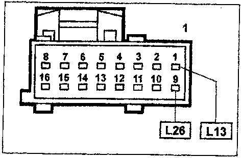
Gearbox sensors/actuators connector (view of contact side)
The resistance of the gear change solenoids S1 and S2 can be measured by disconnect-ing the connector and connecting an ohm-meter as shown in the figure.
Resistence: 13 ± 2 ohm at 20°C
Parts & tools for this job For 1995 Fiat Bravo
- TOOLTorque wrenchSearch: 3/8 inch torque wrench
- TOOLSocket setSearch: socket set metric
- BOOKHaynes manualSearch: Haynes manual Fiat Bravo
Links open Amazon search results in a new tab. As an Amazon Associate I earn from qualifying purchases.