
Front wheel geometry
- Make
- Fiat
- Model
- Bravo /Brava (182) Factory Service Manual
- Year
- 1995–2001
- Section
- Wheel geometry › Front wheel geometry
44 Suspension and wheelsFront wheel geometry · page 1 of 2
FRONT WHEEL GEOMETRY
The wheel geometry must be checked after the components that affect it have been subjected to the following checks:
- tyre pressures;
- the eccentricity and out-of-true of the wheel rims must not exceed 3 mm;
- wheel bearing endfloat;
- clearance between vertical link and wishbone balljoint pin;
- tie-rod end play.
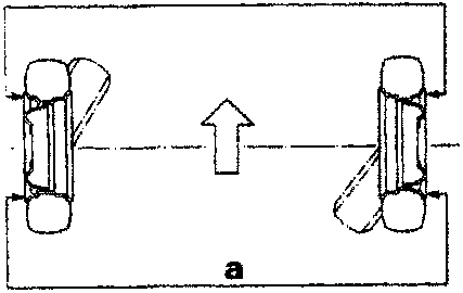
TOE-IN
See data in Sec. 00
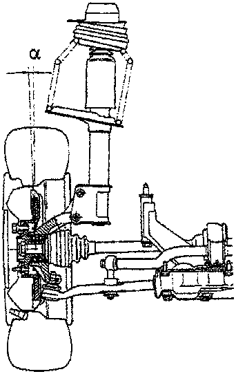
CAMBER (non adjustable)
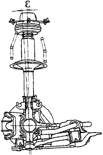
CASTER (non adjustable)
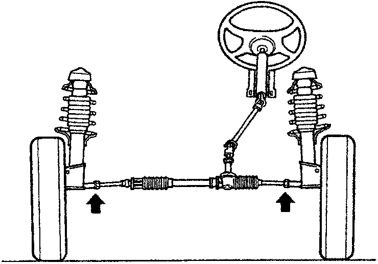
If, when checking the toe-in, the values measured are not as specified, slacken the steering tie-rod nuts and adjust the steering tie-rods.
If the wheel camber angle is not as specified, check the vehicle body shell.
Closely follow the instructions below whenever you adjust the front wheel toe-in:
- undo the clips securing the gaiters on the tie-rods;
- check that the gaiter turns freely on the tie-rod; if necessary remove the gaiter and lubricate with MOLYGUARD SYL 133 silicone grease or a similar product;
- tighten the clip after adjusting the toe-in and only after checking that the gaiter is in the correct position.
Parts & tools for this job For 1995 Fiat Bravo
- TOOLCoil spring compressorSearch: coil spring compressor
- TOOLBall joint separatorSearch: ball joint separator
- PARTFront shock absorbersSearch: Fiat Bravo 1995 front shock absorbers
Links open Amazon search results in a new tab. As an Amazon Associate I earn from qualifying purchases.