
Assembly and refitting
- Make
- Fiat
- Model
- Bravo /Brava (182) Factory Service Manual
- Year
- 1995–2001
- Section
- Manual air conditioner › Assembly and refitting
50 Auxiliary unitsAssembly and refitting
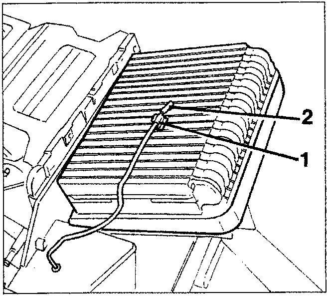
Assembly and refitting
Reverse the procedure described and illustrated for dismantling and removal, bearing in mind the considerations described and illustrated on pages 51 and 52. It should also be borne in mind that the sensitive element (2) of the anti-frost sensor must be positioned at the centre of the finned surface of the evaporator, for which the clip (1) must be fitted on the latter in a suitable position to ensure this.ELECTRIC ACTUATOR FOR POSITIONING AIR INTAKE FLAP
Removing
- remove the dashboard and evaporator-heater-distributor assembly (see Section 70 and preceding pages);
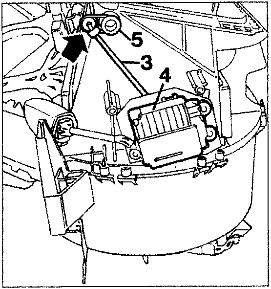
- release the rod (3) connected to the electric actuator (4) from the clip shown by the arrow which secures it to the lever (5) positioning the air intake flap;
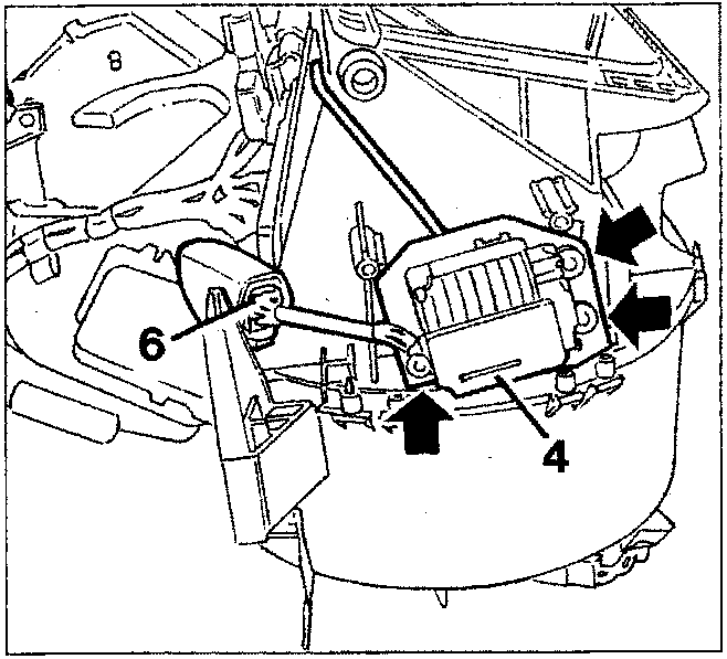
- disconnect the connector (6) from the wiring connector attached to the evaporator-heater-distributor assembly, and undo the screws shown by the arrows in the bottom figure which secure the electric actuator (4) to this assembly;
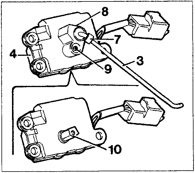
- disengage the rod (3) from the clip (7) and lever (8) and undo the screw (9) securing the latter in a set position on the pin (10) of the actuator (4).
Parts & tools for this job For 1995 Fiat Bravo
- TOOLTorque wrenchSearch: 3/8 inch torque wrench
- TOOLSocket setSearch: socket set metric
- BOOKHaynes manualSearch: Haynes manual Fiat Bravo
Links open Amazon search results in a new tab. As an Amazon Associate I earn from qualifying purchases.