
Draining the system
- Make
- Fiat
- Model
- Bravo /Brava (182) Factory Service Manual
- Year
- 1995–2001
- Section
- Manually operated climate control (98 range) › Draining the system
DRAINING THE SYSTEM
Before carrying out any operation which could result in R 134 A fluid escaping, the climate control system must be drained.
During the operation of draining the system, wear protective gloves and goggles for protection against contact with any jets of R 134 A fluid.
In order to faciliate the draining of the fluid from the vehicle air conditioning system, the engine should be started up and the system left to run for 10-15 minutes before commencing the draining operations.
To drain the vehicle climate control system, use the Cleaner 134 equipment manufactured by ICF and carry out the following operations:
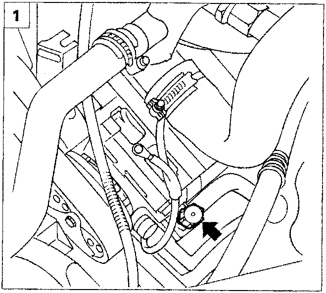
- Undo the plug for the needle valve (low pressure side) which is at the end of a pipe on the pipe which connectors the evaporator to the compressor.
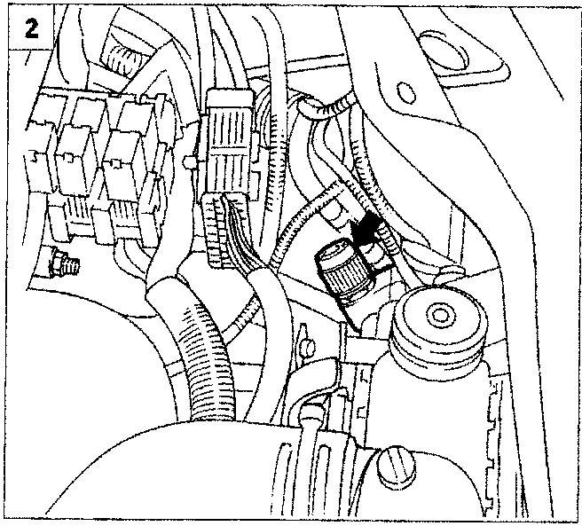
- Undo the plug for the needle valve (high pressure side) which is at the end of a pipe which is an integral part of the connector, at the end of the pipe which connects the condenser to the drier filter.
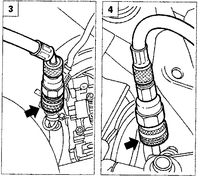
- Fit the rapid attachment connector for the ends of the blue (low pressure side) and red (high pressure side) flexible connecting pipes for the Cleaner R134 equipment on the above mentioned needle valves; then carry out the operations for recovering and recycling the refrigerant fluid descripted and illustrated in the Bravo-Brava 2nd volume Manual (print no. 506.670/01).
NOTE To improve safety, the rapid attachment connectors for the pipes connected to the equipment and the needle valves have different diameters: the low pressure side ones are larger and the high pressure side ones are smaller. Before attaching the rapid attachment connectors to the needle valves, the knurled ring nut shown by the arrow must be moved upwards.
Parts & tools for this job For 1995 Fiat Bravo
- TOOLA/C manifold gauge setSearch: AC manifold gauge set
- TOOLUV leak detection kitSearch: AC UV leak detection kit
- PARTCabin filterSearch: Fiat Bravo 1995 cabin filter
Links open Amazon search results in a new tab. As an Amazon Associate I earn from qualifying purchases.