
Completing assembly
- Make
- Fiat
- Model
- Bravo /Brava (182) Factory Service Manual
- Year
- 1995–2001
- Section
- Air bag › Completing assembly
55 Electrical systemCompleting assembly
Completing assembly
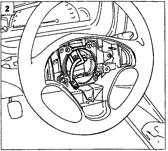
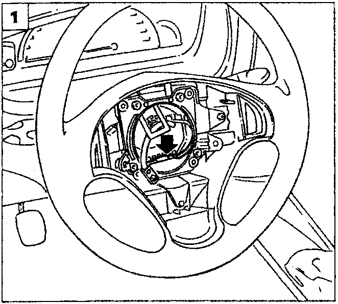
- Fit the connector and connection lead in-to their seat under the horn plate.
- Carefully pass the yellow two-way air bag supply line through the rubber slot.
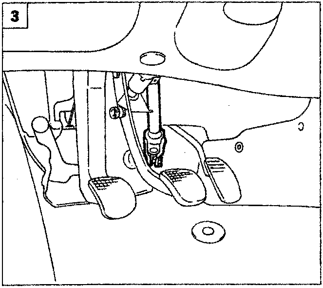
- Release the steering column.
- Diesel versions: tighten the advance handle retaining bolt.
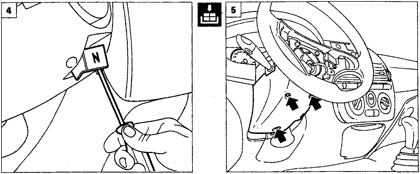
- Refit the lower steering shaft trim and tighten the three cross-headed bolts indi-cated by arrows.
Parts & tools for this job For 1995 Fiat Bravo
- TOOLOBD2 scanner with SRSSearch: OBD2 scanner ABS SRS
- TOOLTrim removal tool kitSearch: trim removal tool kit
Links open Amazon search results in a new tab. As an Amazon Associate I earn from qualifying purchases.