
Manual diagnosis
- Make
- Fiat
- Model
- Bravo /Brava (182) Factory Service Manual
- Year
- 1995–2001
- Section
- Fiat CODE › Manual diagnosis
- For petrol versions with Bosch Motronic system and diesel with electronic fuel injection pump, the Fiat CODE control unit shares the diagnosis line K with the engine control unit (Fig.B). Within the Fiat CODE control unit there is a remote control switch which changes over the connection between the engine control unit and diagnostic socket or Fiat CODE control unit. The switch normally permits dialogue between Fiat CODE control unit and engine control unit (Default condition).
At the start of diagnosis, when the Fiat/Lancia Tester is connected and the ignition is switched on, the Fiat CODE control unit recognizes the diagnosis condition and drives the remote control switch so as to connect pins B5 and B6 to each other, enabling dialogue between the Fiat/Lancia Tester and the engine control unit.
The Fiat CODE control unit permits connection with the Fiat/Lancia Tester only if:
- Thre is no activity on the serial line between the Fiat CODE control unit and the engine control unit.
- There is a low voltage level on pin B5 for a period of time between 500 ms and 5 s (a low level for a period exceeding 5 s is considered to be a short circuit to earth).
The remote control switch returns to the "Default" position when there is no activity on pin B5 for over 30 s.
When the control unit recognizes that the Fiat/Lancia Tester has been connected, it activates the CODE warning light, indicated that the remote control switch has changed over correctly.
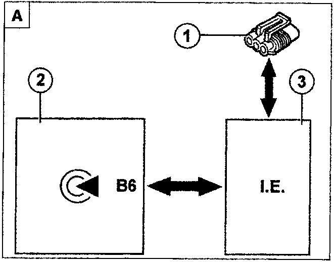
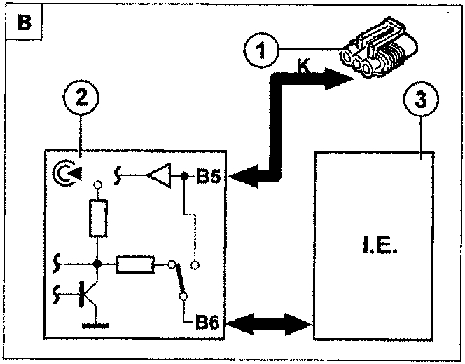
- Diagnostic socket
- Fiat CODE control unit
- Engine control unit
MANUAL DIAGNOSIS
When the CODE warning light stays on permanently with the ignition key at the on position (+15), the problems may be as follows:
- key not recognized by the Fiat CODE control unit;
- serial line not connected;
- key rememorization procedure not carried out correctly (procedure interrupted).
Unused system and ignition on
An unused system means the simultaneous presence on the car of an electronic fuel injection system and a Fiat CODE control unit which do NOT have any memorized codes (for example following an intervention which has required the replacement of both control units). In this case, when the ignition is switched on, the CODE warning light can indicate one of the following conditions also shown on the diagram below:
- When the CODE warning light comes on for 0.7 seconds and after about 2 seconds it starts flashing, everything is properly connected and working, the car is not protected, the universal code is active.
- When the CODE warning light flashes with code 1 (1 flash, pause, 1 flash, etc.), this means that the serial line is not connected or that the two control units have not succeeded in establishing communication.
Parts & tools for this job For 1995 Fiat Bravo
- TOOLDigital multimeterSearch: automotive digital multimeter
- PARTAssorted fuse kitSearch: car fuse assortment kit
- TOOLWire crimper and connector kitSearch: wire crimper connector kit
Links open Amazon search results in a new tab. As an Amazon Associate I earn from qualifying purchases.