
Engine - position on stand and remove
- Make
- Fiat
- Model
- Doblò Factory Service Manual
- Year
- 2000–2010
- Section
- Engine and power unit › Engine - position on stand and remove
Engine - position on stand and remove
Support the engine suitably in order to work on it safely.
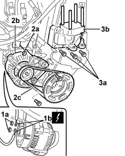
1. Undo the fixing nuts (1a) and disconnect the alternator wiring (1b).
| Description | Connector | |
|---|---|---|
| 1b | Alternator | See A010 ALTERNATOR |
2. Undo the bolt and the nuts (2a) fixing the alternator to the mounting, then remove the alternator assembly (2b) together with the auxiliary drive belt (2c).
3. Undo the fixing bolts (3a) illustrated and remove the rigid engine support (3c).
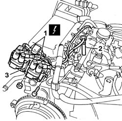
1. Disconnect the electrical connections for the ignition coils.
| Description | Connector | |
|---|---|---|
| 1 | ignition coils | See A30 IGNITION 'COIL ( ENGINE ) |
2. Disconnect the high tension leads from the spark plug seats.
3. Remove the ignition coil.
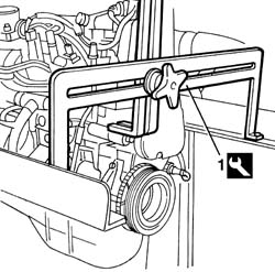
Secure and support the engine using a hydraulic hoist fitted with chains.
1. Position the engine mounting bracket on the timing side.
| Description | Code | |
|---|---|---|
| 1 | Bracket | 1.861.001.032 |
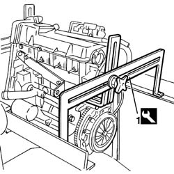
1. Position the engine mounting bracket on the flywheel side.
| Description | Code | |
|---|---|---|
| 1 | Bracket | 1.861.001.034 |
Fasten the engine to the overhaul stand using service bolts.
Release the engine from the chains.
Secure and support the engine using a hydraulic hoist fitted with chains.
Undo the retaining bolts and remove the engine mounting brackets from the rotating stand.
| Description | Code | |
|---|---|---|
| Bracket | 1.861.001.032 |
| Description | Code | |
|---|---|---|
| Bracket | 1.861.001.034 |
Undo the fastenings and remove the supporting tools from the engine, then replace them.
Fit the ignition coil.
Fit the spark plug high tension leads in their seats.
Connect the ignition coil electrical connection.
| Description | Connector | |
|---|---|---|
| ignition coils | See A30 IGNITION 'COIL ( ENGINE ) |
Position the alternator in the special housing and screw in the fixing nuts and bolts without tightening them.
Connect the alternator leads and tighten the fixing nuts.
| Description | Connector | |
|---|---|---|
| Alternator | See A010 ALTERNATOR |
Check the condition of the belt and in particular make sure that there are no cuts, cracks, surface wear of the material, dry sections or hardening which would result in a loss of adhesion. If any one of the above defects is present, replace the belt.
Fit the alternator drive belt on the pullies.
Rotate the alternator in an anti-clockwise direction and secure it using the fixing bolts.
1. Using the tool (1a), check that the belt (1b) tension is between the recommended values.
| Description | Code | |
|---|---|---|
| 1a | Torque wrench | 1.895.762.000 |
| Measurement | Value | ||
|---|---|---|---|
| Alternator new belt tension (daN) | 48 - 60 |
| Measurement | Value | ||
|---|---|---|---|
| Alternator used belt tension (daN) | 30 - 41 |
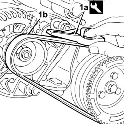
Tighten the lower alternator retaining bolt to torque.
| Fastening | Component | dia | Value (daNm) | |
|---|---|---|---|---|
| Bolt | ALTERNATOR ASSEMBLY | M12 | 8 |
Tighten the upper alternator retaining bolt to torque (slotted area).
| Fastening | Component | dia | Value (daNm) | |
|---|---|---|---|---|
| Bolt | ALTERNATOR ASSEMBLY | M10 | 5 |
Tighten the upper alternator retaining nut to torque.
| Fastening | Component | dia | Value (daNm) | |
|---|---|---|---|---|
| Nut | ALTERNATOR ASSEMBLY | M10 | 5 |
Position the rigid engine support.
Tighten the bolts securing the rigid engine mount to the cylinder block/crankcase to torque.
| Fastening | Component | dia | Value (daNm) | |
|---|---|---|---|---|
| Bolt | RIGID ENGINE MOUNT, TIMING SIDE | M10 X 1.25 | (Engine) 6 |
| Fastening | Component | dia | Value (daNm) | |
|---|---|---|---|---|
| Bolt | RIGID ENGINE MOUNT, TIMING SIDE | M8 X 1.25 | (Engine) 2.2 |
Removing
Support the engine suitably in order to work on it safely.
1. Loosen the bolts fixing the air conditioning compressor drive belt tensioner.
2. Undo the micrometric screw (2a) and the adjustment nut (2b) to discharge the belt tension.
3. Remove the air conditioning compressor drive belt.
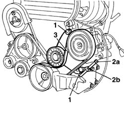
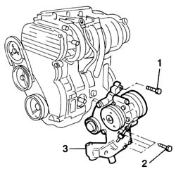
1. Undo the bolt fixing the air conditioning compressor to the intake manifold.
2. Undo the bolts securing the rigid mount to the cylinder block/crankcase.
3. Remove the air conditioning compressor complete with rigid support and belt tensioner.
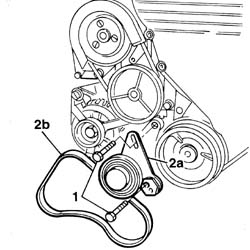
1. Undo the bolts fixing the belt tensioner.
2. Release the belt tensioner, then remove the belt tensioner (2a) together with the alternator drive belt (2b).
1. Undo the fixing bolts.
Disconnect the alternator leads.
2. Remove the alternator from the engine.
| Description | Connector | |
|---|---|---|
| Alternator | See A010 ALTERNATOR |
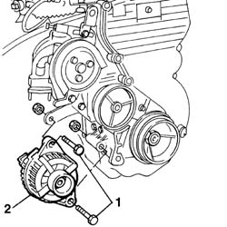
Undo and remove the oil filter.
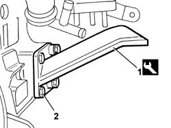
1. Position the inlet side bracket for supporting the engine during overhauling.
| Description | Code | |
|---|---|---|
| 1 | Bracket | 1.861.042.000 |
2. Secure it to the cylinder block/crankcase using service bolts.
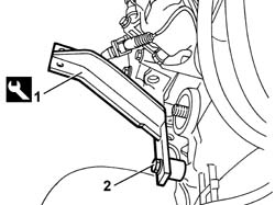
1. Position the exhaust side bracket for supporting the engine during overhauling.
2. Tighten the fixing bolts.
| Description | Code | |
|---|---|---|
| 1 | Bracket | 1.861.042.000 |
Fit the engine on the rotating overhaul stand securing it using service bolts.
Remove the engine mounting chains.
Refitting
Place the mounting chains in the special anchorage points checking that the engine is balanced.
Undo the retaining bolts and remove the engine mounting brackets from the rotating stand.
| Description | Code | |
|---|---|---|
| Bracket | 1.861.042.000 |
Fit the oil filter securing it manually.
Fit the alternator in the special housing and screw in the fixing bolts without tightening them.
Connect the alternator leads.
| Description | Connector | |
|---|---|---|
| Alternator | See A010 ALTERNATOR |
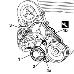
1. Fit the belt tensioner.
2. Tighten the fixing bolts.
3. Fit the alternator drive belt on the pullies.
4. Rotate the tensioner using the hexagonal opening (1a), then check that the belt tension is correct using the tool (1b).
| Description | Code | |
|---|---|---|
| 1b | Torque wrench | 1.895.762.000 |
| Measurement | Value | ||
|---|---|---|---|
| tension check (daNm) | 52 - 67 |
Fit the air conditioning compressor complete with rigid support and belt tensioner.
Tighten the bolts securing the rigid mount to the cylinder block/crankcase.
| Fastening | Component | dia | Value (daNm) | |
|---|---|---|---|---|
| Bolt | RIGID ENGINE MOUNT, TIMING SIDE | M10 X 1.25 | (engine side) 7 |
| Fastening | Component | dia | Value (daNm) | |
|---|---|---|---|---|
| Bolt | RIGID ENGINE MOUNT, TIMING SIDE | M10 X 1.25 | (engine side) 2.5 |
Tighten the bolt fixing the air conditioning compressor to the intake manifold to torque.
1. Fit the air conditioning compressor drive belt.
2. Using the micrometric screw (2a) and the adjustment nut (2b), tension the air conditioning compressor drive belt.
3. Lock the bolts fixing the air conditioning compressor drive belt tensioner.
Use a torque wrench to check that the belt tension is correct.
| Description | Code | |
|---|---|---|
| Torque wrench | 1.895.762.000 |
| Measurement | Value | ||
|---|---|---|---|
| tension check (daN) | 42 - 55 |
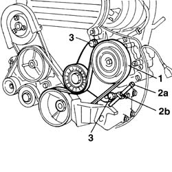
Tighten the tensioner fixing bolts.
Remove the hooks and supports positioned previously.
SOLUTION A
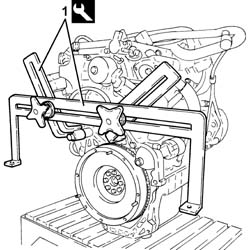
1. Fit the two brackets for the universal tool.
| Description | Code | |
|---|---|---|
| 1 | Bracket | 1.861.001.034 |
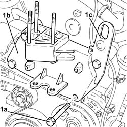
1. Undo the bolts (1a) and remove the timing side rigid engine support (1b) complete with engine lifting bracket (1c).
1. Fit the two brackets for the universal tool.
| Description | Code | |
|---|---|---|
| 1 | Bracket | 1.861.001.032 |
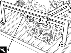
Secure and support the engine using a hydraulic lift fitted with chains.
Position the engine on the overhaul stand using the universal tool fitted previously.
| Description | Code | |
|---|---|---|
| Rotating stand | 1.861.000.000 |
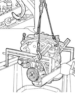
Release the engine from the hydraulic lift.
Secure and support the engine using a hydraulic lift fitted with chains.
Undo the fastenings securing the universal tool to the overhaul stand, then position the enigne on a special workbench using the hydraulic lift.
Undo the fastenings and remove the universal tool from the engine.
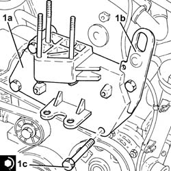
1. Place the timing side rigid engine support (1a) in its housing with the engine lift bracket (1b) and secure it tightening the bolts (1c) to the recommended torque.
| Fastening | Component | dia | Value (daNm) | |
|---|---|---|---|---|
| 1c | Bolt | RIGID ENGINE MOUNT, TIMING SIDE | M10 | (Engine upper crankcase side) 5.7 - 6.3 |
SOLUTION B
1. Keep the flywheel lock fitted
Op. 1004d10 POWER UNIT (MANUAL GEARBOX), REMOVED, REMOVE AND RE-BUILD
| Description | Code | |
|---|---|---|
| 1 | Counter-torque | 1.860.846.000 |
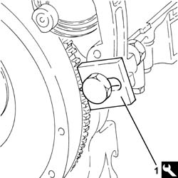
1. Loosen the bolts fixing the crankshaft pulley.
2. With the engine tuned
Op. 1004d10 POWER UNIT (MANUAL GEARBOX), REMOVED, REMOVE AND RE-BUILD
loosen the left hand thread bolt securing the pulley mounting flange to the crankshaft.
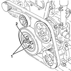
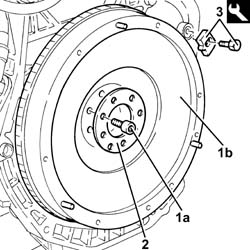
1. Undo the bolts (1a) and remove the engine flywheel (1b).
2. Remove the flange.
The bolts fixing the flywheel are pre-treated with sealant, therefore they should be replaced each time they are removed.
3. Remove the flywheel lock.
| Description | Code | |
|---|---|---|
| 3 | Counter-torque | 1.860.846.000 |
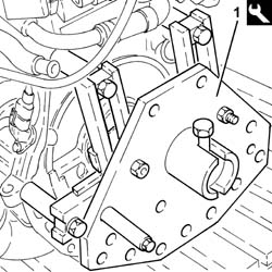
1. Fit the universal tool on the engine block.
| Description | Code | |
|---|---|---|
| 1 | Rotary stand for overhauling | 1.871.001.000 |
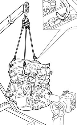
Secure and support the engine using a hydraulic lift fitted with chains.
Position the engine on the overhaul stand using the universal tool fitted previously.
Release the engine from the hydraulic lift.
Secure and support the engine using a hydraulic lift fitted with chains.
Undo the fastenings securing the universal tool to the overhaul stand, then position the enigne on a special workbench using the hydraulic lift.
Undo the fastenings and remove the universal tool from the engine.
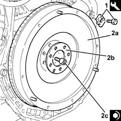
1. Fit the flywheel lock.
| Description | Code | |
|---|---|---|
| 1 | Counter-torque | 1.860.846.000 |
2. Place the engine flywheel (2a), complete with flange (2b), back in its housing and secure it tightening the new bolts (2c) to the recommended torque.
| Fastening | Component | dia | Value (daNm) | |
|---|---|---|---|---|
| 2c | Bolt | FLYWHEEL (MECH.) | M8 | (Crankshaft side) 4.0 - 4.8 |
1. With the timing template fitted on the exhaust side camshaft
Op. 1004d10 POWER UNIT (MANUAL GEARBOX), REMOVED, REMOVE AND RE-BUILD
, proceed with tightening the left hand thread bolt securing the pulley mounting flange to the crankshaft.
| Fastening | Component | dia | Value (daNm) | |
|---|---|---|---|---|
| 1 | Anticlockwise bolt | PULLEY SUPPORT FLANGE ON CRANKSHAFT | M14 | (Crankshaft side) 21.9 - 24.2 |
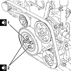
2. Tighten the bolts fixing the crankshaft pulley to the recommended torque.
| Fastening | Component | dia | Value (daNm) | |
|---|---|---|---|---|
| 2 | Bolt | CRANKSHAFT PULLEY | M8 | (Crankshaft flange side) 2.3 - 2.8 |
Rest the engine on a workbench.
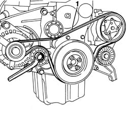
Adjust the automatic belt tensioner using the tool to slacken the auxililary drivebelt.
1. Remove the single engine components drive belt (1).
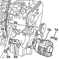
1. Undo the bolts (1a) and remove the alternator (1b) after having disconnected the electrical connections.
2. Undo the bolts (2a) and remove the alternator rear mounting bracket (2b).
3. Undo the fixing bolts (3a) and detach the oil dipstick introduction pipe (3b).
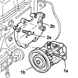
1. Undo the bolts (1a) and remove the air conditioner compressor (1b).
2. Undo the bolts (2a) and remove the air conditioning compressor mounting (2b).
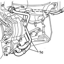
1. Loosen the bands (1a) and the connector (1b) and detach the coolant pipes (1c).
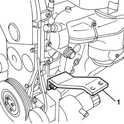
1. Fit the tool for supporting the engine on the overhaul stand, front engine side.
| Description | Code | |
|---|---|---|
| 1 | Brackets | 1.861.001.039 |
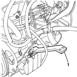
1. Fit the tool for supporting the engine on the overhaul stand, rear engine side.
| Description | Code | |
|---|---|---|
| 1 | Brackets | 1.861.001.039 |
Secure and support the engine using a hydraulic hoist fitted with chains.
Fit the engine on the overhaul stand.
Release the engine from the hoist.
Drain the engine oil from the plug on the oil sump.
Secure and support the engine using a hydraulic hoist fitted with chains.
Undo the fastenings and remove the engine from the overhaul stand complete with supporting tools.
Rest the engine on a workbench.
Release the engine from the hoist.
Undo the fastenings and remove the support tool.
| Description | Code | |
|---|---|---|
| 1 | Brackets | 1.861.001.039 |
Fit the air conditioning compressor support and secure it using the bolts.
| Fastening | Component | dia | Value (daNm) | |
|---|---|---|---|---|
| Bolt | Air conditioning compressor support | M10 | 5 |
Fit the air conditioning compressor and secure it using the bolts.
| Fastening | Component | dia | Value (daNm) | |
|---|---|---|---|---|
| Bolt | AIR CONDITIONER ASSEMBLY COMPRESSOR | M8 | 2.5 |
Fit the rigid coolant pipes.
Fit the engine oil dipstick tube introduction pipe.
Fit the alternator rear mounting bracket and secure it using the bolts without tightening them.
Fit the alternator and fasten it using the bolts.
| Fastening | Component | dia | Value (daNm) | |
|---|---|---|---|---|
| Nut | ALTERNATOR ASSEMBLY | M10 X 1.25 | 5 |
| Fastening | Component | dia | Value (daNm) | |
|---|---|---|---|---|
| Nut | ALTERNATOR ASSEMBLY | M12 X 1.25 | 7 |
Tighten the alternator rear mounting bracket bolts.
Fit the auxiliary drivebelt by using a wrench as a lever on the automatic belt tensioner.
Removing
Rest the engine on a workbench.
Remove any wiring remaining on the engine.
Adjust the automatic belt tensioner using the tool to slacken the auxililary drivebelt.
1. Remove the single engine components drive belt (1).
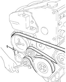
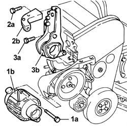
1. Undo the bolts (1a) and remove the alternator (1b).
2. Undo the bolts (2a) and remove the alternator rear mounting bracket (2b).
3. Undo the bolts (3a) and remove the intermediate shaft support (3b).
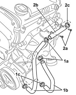
1. Remove the bands (1a) and (1c) and disconnect the water supply and return pipes (1b) to the heater exchanger.
2. Remove the band (2c) and undo the bolts (2a), then disconnect the rigid water outlet pipe (2b) for the water-oil heat exchanger from the manifold.
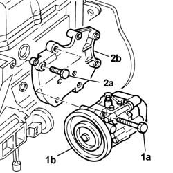
1. Undo the bolts (1a) and remove the air conditioner compressor (1b).
2. Undo the bolts (2a) and remove the air conditioning compressor mounting (2b).
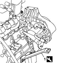
1. Fit the tool for supporting the engine on the overhaul stand.
| Description | Code | |
|---|---|---|
| 1 | Brackets | 1.861.001.039 |
Secure and support the engine using a hydraulic hoist fitted with chains.
Fit the engine on the overhaul stand.
Release the engine from the hoist.
Drain the engine oil from the plug on the oil sump.
Refitting
Secure and support the engine using a hydraulic hoist fitted with chains.
Undo the fastenings and remove the engine from the overhaul stand complete with supporting tools.
Rest the engine on a workbench.
Release the engine from the hoist.
Undo the fastenings and remove the support tool.
| Description | Code | |
|---|---|---|
| 1 | Brackets | 1.861.001.039 |
Fit the air conditioning compressor support and secure it using the bolts.
Fit the air conditioning compressor and secure it using the bolts.
Connect the supply and return pipes to the water-oil heat exchanger.
Tighten the bolt for the water supply pipe bolt to the water/oil heat exchanger.
Connect the water/oil heat exchanger coolant supply pipe to the thermostat cup
Fit the intermediate shaft support and secure it using the bolts.
Fit the alternator rear mounting bracket and secure it using the bolts without tightening them.
Fit the alternator and fasten it using the bolts.
Tighten the alternator rear mounting bracket bolts.
Fit the auxiliary drive belt and tension it using a wrench as a lever on the automatic belt tensioner.
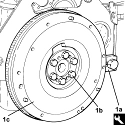
1. Fit the flywheel lock (1a), unscrew the bolts (1b) and remove the engine flywheel (1c)
| Description | Code | Function | |
|---|---|---|---|
| Counter-torque | 1.860.846.000 | Flywheel lock |
- Remove the flywheel lock.
| Description | Code | Function | |
|---|---|---|---|
| Counter-torque | 1.860.846.000 | Flywheel lock |
- Remove the centring bush guard.
- Fit the mount on the crankcase.
| Description | Code | Function | |
|---|---|---|---|
| Overhaul stand | 1.871.000.000 | Overhaul engine |
- Using the tool and a hydraulic lift, place the engine on the overhaul stand.
| Description | Code | Function | |
|---|---|---|---|
| Overhaul stand | 1.871.000.000 | Overhaul engine |
- Support the engine using the tools and a hydraulic lift.
- Undo the bolts fixing the engine block to the overhaul stand support.
- Position the flywheel guard and fit the engine flywheel.
- Fit the flywheel lock.
| Description | Code | Function | |
|---|---|---|---|
| Counter-torque | 1.860.846.000 | Flywheel lock |
- Tighten the new bolts securing the engine flywheel to the recommended torque.
| Value daNm | Fastening | Component | dia | |
|---|---|---|---|---|
| 4.0 ÷ 4.8 | Bolt (to be replaced) | Engine flywheel | M8 |
Parts & tools for this job For 2000 Fiat Doblò
- PARTEngine gasket setSearch: Fiat Doblò 2000 engine gasket set
- TOOLTorque wrenchSearch: 3/8 inch torque wrench
- TOOLFeeler gauge setSearch: feeler gauge set
Links open Amazon search results in a new tab. As an Amazon Associate I earn from qualifying purchases.