
Introduction - clutch
- Make
- Fiat
- Model
- Grande Punto Factory Service Manual
- Year
- 2005–2012
- Section
- General › Introduction - clutch
INTRODUCTION - CLUTCH
CONSTRUCTION SPECIFICATIONS
The clutch is single dry plate type, with a thrust bearing in permanent contact with the pressure spring.
The driven plate is driven by pressure exercised by a diaphragm spring. The clutch release takes place via the hydraulic system operated by the pedal.
On all versions friction materials free from non-environmentally friendly components have been adopted; special care has been taken in the development of new materials and the clutch assembly with a view to guaranteeing excellent performance in terms of modulation and driving comfort with a consequent reduction in weight compared with traditional hydraulic operation. The clutch pump has undergone considerable improvements compared with the components used normally; it comprises:
- plastic casing which makes a further contribution to a reduction in the weight;
- steel cylinder;
- plastic material piston.
The material for the piston and the rubber seals have been specially developed for operating with long strokes; in addition, the seal produced by the rubber-steel contact is excellent compared with traditional type clutch pumps where the seal is on cast iron.
COMPOSITION
The system consists of:
- a clutch pump (master cylinder) (2) fastened to the pedals assembly that compresses the oil;
- a pipe (3) connecting the pump and the clutch operating cylinder;
- a clutch operating cylinder (4) fastened to the gearbox;
- linkage (5) operating the thrust bearing;
- a thrust bearing (6);
- a clutch drip tray with diaphragm springs (7);
- a clutch plate (8);
- a fluid reservoir (1) shared with the braking system.
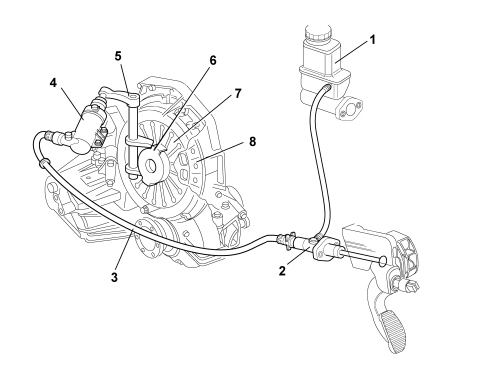
1. Brake/clutch fluid reservoir
2. Clutch pump
3. Pipe connecting pump and cylinder
4. Clutch operating cylinder
5. Linkage
6. Thrust bearing
7. Diaphragm spring
8. Clutch plate
OPERATION
The pump (2), operated by the clutch pedal, pressurizes the hydraulic circuit and operates the clutch control cylinder (4).
The latter acts on the linkage (5) which "pulls" the thrust bearing (3), overcoming the action of the pressure plate springs (7).
This action causes the release of the clutch plate (8) from the flywheel.
When the pedal is released, the action of the diaphragm springs (7) returns the mechanism to the original position.
CONSTRUCTION SPECIFICATIONS
The clutch release system has a coaxial hydraulic control combined with a device for the recovery of the clutch plate wear which allows the load on the clutch pedal to remain constant throughout the life of the vehicle
The clutch release shaft, the bushes, the clutch release external lever and the clutch control cylinder (actuator) are eliminated with this type of control.
The system is known as co-axial because the release actuator consists of an aluminium ring cylinder, fitted inside the clutch bellhousing, positioned between the gearbox and the clutch mechanisms, co-axially in relation to the main shaft.
The advantage of this system compared with conventional systems lies in the absence of kinematic couplings resulting in improved reliability and functionality, making it easy to maintain. The system features the following characteristics:
- constant adjustment of the clutch pedal setting;
- constant force applied to the pedal over a period of time;
- elimination of any difficulties with the clutch pedal return;
- reduction in the noise and vibrations transmitted by the pedal.
The connection of the pipe to the actuator is produced by means of a rapid connector with an integrated bleed and "clip" type attachments for quick and easy release/reattachment for maintenance operations.
The absence of the traditional system idler crank and the adoption of plastic materials for the construction of the pedal assembly has also allowed a considerable reduction in noise and the overall weight of the system.
In particular the clutch pump has undergone a considerable improvement compared with the components usually adopted; it is equipped with:
- plastic casing with a further contribution to the reduction in the weight;
- steel cylinder;
- plastic material piston.
The material of the piston and the rubber seals have been developed specifically to operate with long strokes; in addition the seal produced by the rubber-steel contact is excellent compared with traditional type clutch pumps where the seal was produced on cast iron.
The clutch release takes place through the action of the clutch pump which sends oil, under pressure, via the pipe (4), into the expansion chamber. The pressure of the oil causes the movement of the piston which slides in the guide pipe through the teflon anti-wear pads. The piston is in one piece with the thrust bearing which presses on the pressure plate springs thereby releasing the clutch. As the pressure of the oil ceases, the actuator returns to the rest position through the effect of the pressure plate springs.
The seal against any oil leaks that could emanate from inside the bellhousing is guaranteed by an oil seal and an O-ring.
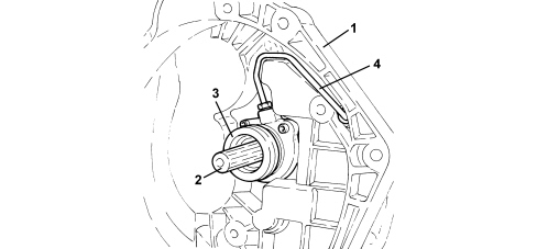
1. Clutch casing
2. Main shaft
3. Hydraulic clutch actuator
4. Fluid pipe
SELF-ADJUSTING CLUTCH
The clutch has a clutch plate wear recovery device known as SAC.
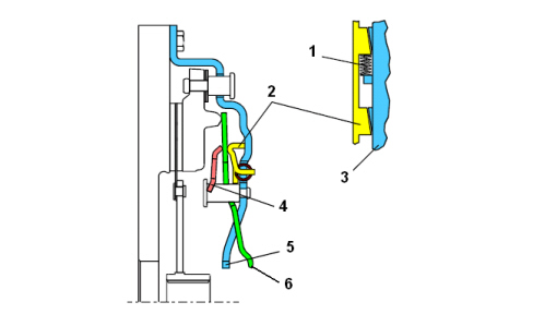
1. Movement spring
2. Compensation ring
3. Cover
4. Load sensor
5. Travel restricter
6. Diaphragm spring
The mechanism rests on knurled tilted planes (2). When there is wear, 3 springs (1) cause the seal to rotate which is raied guaranteeing the recovery of the clearance.
This device basically offers the following advantages:
- lasts 50% longer than a traditional clutch;
- limited release forces that remain constant for the entire duration;
- constant position of the clutch pedal;
- restriction of noise and vibrations;
- reduced dimensions for engines with high torque.
TWIN MASS FLYWHEEL
On diesel versions the flywheel is dual mass damping type consisting of two masses, one integral with the crankshaft and the other with the gearbox mainshaft, via the clutch plate. A flexible torsional damping system is created between these two masses with a system of springs (positioned in parallel) with differential stiffness. This main feature of this type of flywheel is its ability, unlike a normal flywheel, to alter the torsional resonance speed to below the engine service speed.
This type of flywheel damps torque fluctuations in two stages to reduce power transmission vibration and roughness in a more effective and targeted manner.
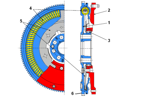
1. Main flywheel
2. Secondary flywheel
3. Roller bearing
4. Arc spring
5. Flange
6. Toothed wheel
CONSTRUCTION SPECIFICATIONS
The clutch release system has a coaxial hydaulic control combined with a device for the recovery of the clutch plate wear which allows the load on the clutch pedal to remain constant throughout the life of the vehicle.
The clutch release shaft, the bushes, the clutch release external lever and the clutch control cylinder (actuator) are eliminated with this type of control.
The system is known as co-axial because the release actuator consists of an aluminium ring cylinder, fitted inside the clutch bellhousing, positioned between the gearbox and the clutch mechanisms, co-axially in relation to the main shaft.
The advantage of this system compared with conventional systems lies in the absence of kinematic couplings resulting in improved reliability and functionality, making it easy to maintain. The system features the following characteristics:
- constant adjustment of the clutch pedal setting;
- constant force applied to the pedal over a period of time;
- elimination of any difficulties with the clutch pedal return;
- reduction in the noise and vibrations transmitted by the pedal.
The connection of the pipe to the actuator is implemented through a rapid connector with a built in bleed and clip type mountings that guarantee rapid and simple release/attachment for maintenance operations.
The absence of a conventional system idler crank and the adoption of plastic materials for the construction of the pedal assembly has also allowed a considerable reduction in noise and in the overall weight of the system.
The clutch pump has undergone considerable improvements compared with the components used normally; it comprises:
- plastic casing which makes a further contribution to a reduction in the weight;
- steel cylinder;
- plastic material piston.
The material for the piston and the rubber seals have been specially developed for operating with long strokes; in addition, the seal produced by the rubber-steel contact is excellent compared with traditional type clutch pumps where the seal is on cast iron.
The clutch release takes place through the action of the clutch pump which sends oil, under pressure, via the pipe (4), into the expansion chamber. The pressure of the oil causes the movement of the piston which slides in the guide pipe through the teflon anti-wear pads. The piston is in one piece with the thrust bearing which presses on the pressure plate springs thereby releasing the clutch. As the pressure of the oil ceases, the actuator returns to the rest position through the effect of the pressure plate springs.
The seal against any oil leaks that could emanate from inside the bellhousing is guaranteed by an oil seal and an O-ring.
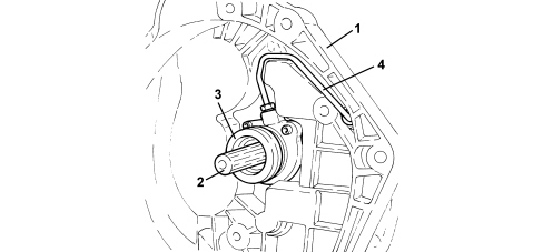
1. Clutch casing
2. Main shaft
3. Hydraulic clutch actuator
4. Fluid pipe
SELF-ADJUSTING CLUTCH
The clutch has a device for recovering wear of the clutch plate known as SAC.
1. Movement spring
2. Compensation ring
3. Cover
4. Load sensor
5. Travel restricter
6. Diaphragm spring
The mechanism rests on knurled tilted planes (2). When there is wear, 3 springs (1) cause the seal to rotate which is raied guaranteeing the recovery of the clearance.
This device basically offers the following advantages:
- lasts 50% longer than a traditional clutch;
- limited release forces that remain constant for the entire duration;
- constant position of the clutch pedal;
- restriction of noise and vibrations;
- reduced dimensions for engines with high torque.
TWIN MASS FLYWHEEL
On diesel versions the flywheel is dual mass damping type consisting of two masses, one integral with the crankshaft and the other with the gearbox mainshaft, via the clutch plate. A flexible torsional damping system is created between these two masses with a system of springs (positioned in parallel) with differential stiffness. This main feature of this type of flywheel is its ability, unlike a normal flywheel, to alter the torsional resonance speed to below the engine service speed.
This type of flywheel damps torque fluctuations in two stages to reduce power transmission vibration and roughness in a more effective and targeted manner.
1. Main flywheel
2. Secondary flywheel
3. Roller bearing
4. Arc spring
5. Flange
6. Toothed wheel
Parts & tools for this job For 2005 Fiat Grande Punto
- PARTClutch kitSearch: Fiat Grande Punto 2005 clutch kit
- TOOLClutch alignment toolSearch: clutch alignment tool
- FLUIDGear oilSearch: Fiat Grande Punto manual gearbox oil
Links open Amazon search results in a new tab. As an Amazon Associate I earn from qualifying purchases.