
Introduction - FITTINGS
- Make
- Fiat
- Model
- Stilo Factory Service Manual
- Year
- 2001–2007
- Section
- General › Introduction - FITTINGS
Introduction - FITTINGS
SPECIFICATIONS
The layout of the panel functional elements has been designed to allow the correct interaction with the body of the occupant in the case of a side impact.
They are soft and smooth in the top section, whilst the protrusion of the armrest is made harmless by the fact that it collapses and presents no risk of injury to the abdomen. The door also features a Carrier which, in addition to supporting the electric window motor, guides and various cables, is integrated with the actual door and performs a structural function.
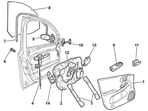
1 - Door inner panel
2 - Carrier
3 - Electric window guides
4 - Opening mechanism bowden cable
5 - Rear view mirror
6 - Door lock catch
7 - Seal
8 - Window
9 - Door control panel
10 - Door check strap
11 - Door interior opening handle
12 - Electric window motor
13 - Door node
14 - Lock
INTRODUCTION
All vehicles can be fitted as an option with a laminated glass sun roof which can be operated by a remote control on certain versions.
The laminated glass sun roof and electronically adjusted PVC blind make it possible to provide excellent light for the passenger compartment when the roof is closed and an intake of air when it is open through the six possible adjustment positions.
The system is also fitted with an anti-crush safety device which stops the movement of the roof if there are any obstacles present.
SPECIFICATIONS:
The sun roof assembly consists of a system of mechanism which adjust the position of the five glass plates reinforced by an aluminium frame. The sun roof is opened by an electric motor and adjusted through a 6 position selector ( including zero '0'); in particular, the first roof plate has a rocker movement whilst the other 4 plates have a traversing movement.
The sun roof system is also fitted with a sliding sun blind (electronically operated by a second electric motor) whose opening cannot be lower than the opening of the actual plates.
The selection controls are located in the centre courtesy light and are managed by two control unit (master for the front and slave for the rear) which interact with each other controlling the action of the two built-in motors at the longitudinal edges of the roof.
The movement mechanisms are fitted in the aluminium guides and driven by a clock spring operated by the front electric motor.
There are also drainage channels on the four front and rear sides of the frame which drain off water that could filter from the seals through pipes with anti-reflux valves (which will probably be eliminated).
Safety is guaranteed by an anti-crush system which is activated for the entire range of movement when both the sun blind and the roof are being closed.
COMPOSITION
The sun roof consists of:
- a frame comprising two aluminium guides in which the movement mechanisms slide and two crossmembers, front and rear, made from plastic which define the width of the roof and complete the frame
- a right and left mechanism system, fitted in the aluminium guides, for moving the glass plates
- a sliding PVC roller sun blind with metal reinforcement ribs and a an aluminium profile front crossmember which slides along the entire length of the roof and is operated by a second electric mitor;
- five reinforced glass plates, each with a frame;
- two electric movement motors which interact with one another through the respective built-in control units (motor current absorption: when moving plates and blind about 10A per motor)
The diagram below shows the laminated sun roof opening system.
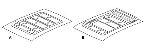
1 Control panel
2 First plate selector in tilt position
OPERATION
The operating logic described below is achieved through the action of two electric motors managed by two electronic control units (known as Master and Slave) which control the laminated glass roof and the sun blind, respectively.
The sun roof moves along the sliding guides, positioned on the frame, through a bowden cable (rack) operated by an electric motor located in the front part of the roof frame. The action of the motor causes the vertical movement of the lift lever for the first plate which produces the two permitted positions for the spoiler, later on the cable acts on the attachment brackets for the other plates moving them until the total permitted opening is completed.
The sun roof is fitted with a sun blind underneath which can be operated indepdently (with the plates closed) using the two buttons on the courtesy light and/or automatically through the (Master) control unit which, when the sun roof is opening, co-ordinates the alignment of the blind with the opening position of the second plate. The closing of the blind is subject to the opening position of the plates: the blind cannot, in effect, be closed with the glass open.
The sun roof may be moved manually by means of the selector under the following conditions:
- with the ignition key in the Key On position
- the roof can be moved remotely, i.e. when the control unit receives the control signals from the Body Computer.
The Master Control Unit is connected in series to the Body Computer therefore a problem with the latter will affect the roof operating logic.
The anti-crush safety function is always active during movement, slide/tilt operations (including operations controlled remotely).
Do not disconnect the battery or supply the sun roof with power during motion. If this happens, the control units lose their memory and must be reset as described in the Chapter 'Resetting Control Unit Memory' up to step 3.
ANTI-CRUSH FUNCTION
In order to limit possible damage to passengers or objects whilst the roof is moving, an anti-crush safety function is included. The safety system is present for the entire blind closing range on the front profile of the second plate during sliding and on the rear edge of the first plate during tilting.
After detecting a force which is greater than a pre-set level, the Master Control Unit (fitted at the front) which governs the roof plates, immediately stops the movement in the case of the first plate and completely reverses the tilting movement, whilst in the case of the second plate it orders the immediate halting and reversal of the movement for a travel of 200 mm.
The function is also activated during closure on the front profile of the blind and is operated by the Slave Electronic Control Unit (fitted at the rear) after an obstacle (e.g. finger, hand) is encountered, guaranteeing the reversal of the movement for a travel of 200 mm.
The anti-crush safety function can be excluded by placing the selector in the inhibitor position which works within 5 secs. After the roof has stopped, when the rotary selector is pressed in position '0' the control remains activated until the roof is closed or until the selector is released: in this case the function is not activated.
SELECTOR AND CONTROL PANEL
The controls, located in the centre courtesy light, include the six position rotary selector (including '0') (clockwise direction for opening, five positions and anti-clockwise direction for closing) and the two one-touch type blind opening/closing buttons
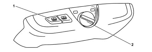
A - Opening of first plate in tilt position
B - Sliding of other plates
SELECTOR AND CONTROL PANEL
CONTROL PANEL:
- The two buttons open and close the blind
- if either button is pressed again the blind stops in the desired position
SELECTOR POSITIONS:
- 0 roof completely closed
- 1 minimum tilt position for first plate
- 2 - maximum tilt position for first palte and second plate retracted
- 3 - 5 sliding positions for second plate and other plates retracted
The opening/closing of the sun blind is subject to the position of the glass plates. Whilst the plates are opening the blind moves automatically reaching a position where it covers the glass when it is completely open, whilst during closure the blind is about 30 mm ahead of the second plate and stops 30 mm from the end of travel position.
CONTROL UNITS
The table below summarizes the functions of the two control units
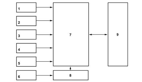
1 - ANTI-CRUSH FUNCTION
2 - OPENING/CLOSING ROOF USING SELECTOR
3 - SPEEDOMETER SIGNAL
4 - LIGHTING SIGNAL
5 - MANUAL BLIND CONTROL
6 - ROOF CLOSING REMOTE CONTROL
7 - MASTER ELECTRONIC CONTROL UNIT (ROOF)
8 - BODY COMPUTER NODE
9 - SLAVE ELECTRONIC CONTROL UNIT (BLIND)
CONTROL UNITS
The movement of the sun roof and the blind is governed by the Master Control Unit which manages a second Slave Control Unit both of which are housed in casings on the motor. These electric devices process the signals coming from either the selector/control panel or the remote control, through the Body Computer and also control the anti-crush safet function.
The function is controlled by the control unit, which receives position and speed information from Hall effect sensors fitted to the motor. When effort in excess of a certain threshold is detected, corresponding to a higher current uptake, this is interpreted as an obstacle. The control unit then stops the roof immediately and moves it back in the opposite direction.
The control unit also receives a vehicle speed signal because the vacuum created at certain speeds could change the effort required to close the roof and under certain conditions this could be interpreted as an impediment. The control unit therefore uses this signal to ensure movement is not halted inadvertantly.
RESETTING THE CONTROL UNIT MEMORY
The initialization procedure must be carried out each time the sun roof control units are changed, whilst if there is a drop in the supply whilst he roof is working (failed supply from the battery) the procedure should be carried out up to step 3.
The initialization procedure is illustrated below:
- 1 turn the rotary selector knob to position '0' (fully closed)
- 2 keep the rotary selector pressed (for longer than 2 secs): the roof closes
- 3 wait, keeping the roof completely closed until the blind has clicked shut twice (Hard closing position and then returns to the Soft closing position)
- 4 release the selector and press it again within 3 secs.
- 5 keep the selector pressed until the roof (glass and blind) is completely open and then closed again
- 6 release the selector;
The initialization is completed at this point.
in the case of repairs to or problems with the Body Computer or a break in the battery connections, the motor absorption may be 26+26 A max
The initialization process cannot not take place successfully if one of the following conditions occurs:
- The rotary selector has not been placed in position '0';
- The selector has ben released during the manoeuvre;
- The blind operating button has been pressed;
If the process has not been successfully concluded it should be repeated.
CONTROL UNIT PIN OUT
Master Control Unit
| PIN NO. | FUNCTION |
|---|---|
| 4 | BATTERY + |
| relay | POWER GND |
| relay | ELECTRONIC GND |
| 6 | SERIAL COMMUNICATION |
| 5 | GL/CLOSED AUTHORIZATION |
| 3 | SPEED SIGNAL |
| 7 | FREE (contact strip 1) |
| 8 | FREE (contact strip 2) |
| 10 | POTI 1 |
| 9 | POTI 2 |
| 12. | POTI 3 |
| 11. | POTI 4 |
Slave Control Unit
| PIN NO. | FUNCTION |
|---|---|
| relay | SERIAL COMMUNICATION |
| 3 | SERIAL COMMUNICATION |
| 5 | BATTERY + |
| 7 | BATTERY + |
| 9 | EARTH |
| 11. | EARTH |
COMPLETE SUN ROOF
During repair operations (replacing the frame or complete roof) or in the case of water or air penetration it may prove necessary to adjust the roof even if this adjustment requires great care and attention.
The procedure is carried out (with the roof secured to the bodyshel by tightening the coaxial screws to the adjusters - 7 Nm) using the 4 adjustment nuts (the roof is raised when they are undone using a 19 mm spanner and lowered micrometrically when they are tightened) located at the ends of the aluminium guides on the actual frame.
In this case it is vital that all the other fastenings (8 self-adjusting and 3 fixed) are fully loosened: if this is not the case, the adjustable fastenings will be irreparably damaged with the 19 mm spanner.
PLATES
During repair operations in the case of water or air penetration, it may prove necessary to adjust the plates even if great care needs to be taken over such an adjustment.
The procedure is carried out by adjusting the 4 screws (two on each section) on the sides of the plate concerned; loosening them allows the plate to be moved about 2 - 3 mm in X and Z (there is no possible movement in Y). The housing for the screws is protected by plastic shields which guarantee a further decrease in wind noise.
If a plate requires adjustment in Z (vertical direction) it is advisable to only loosen the 2 screws (one on the right and the corresponding one of the left) located near the section (front or rear of the actual plate) to be adjusted. Conversely, if the movement required is X (longitudinal to the direction of travel of the vehicle) all 4 of the screws for the plate concerned have to be loosened: in this case the adjustment of a plate may, in some cases, involve the need to adjust all the other plates because this alteration could adversely affect the profile of the plates with further possible aerodynamic wind noise problems.
whilst adjusting the plate no force should be applied to the motor/control unit sub-assemblies
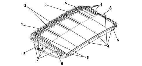
A - Motor and Master Control Unit
B - Motor and Slave Control Unit
1 - Reference Y
2 - 2+2 x 5 Lamellar fastenings
3 - References X-Y
4 - 8 Self-adjusting fastenings
5 - Roof fastenings (adjustable with 19 mm spanner)
6 - Blind support
7 - Fastenings (without adjustments)
EMERGENCY MANOEUVRE
If the electric movement device fails to operate, the sun roof may be moved manually using the emergency key where the torque required is about 6.5 Nm.
The key is located in the courtesy light near the control unit housing.
ELECTRIC MOTORS
The electric motors are located at the edges of the roof and control the movement of the roof (front motor) and the movement of the sun blind (rear motor), respectively.
The dismantling system in order to remove the main motor requires the roof to be completely closed (use the manual key if the roof is open) and the frame removed whilst the second electrical device is fitted on the plastic support which projects is relation to the rear crossmember.
SPECIFICATIONS
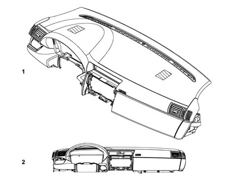
When designing the dashboard for this vehicle both aesthetics and passive safety have been taken into consideration.
The soft material covering the dashboard and the distance of the crossmember connecting the pillars guarantee optimum support for absorbing any impact energy of the head against the dashboard at minimal force levels.
The lower part of the dashboard has been designed to ensure that there is no contact between the passengers knees and any rigid parts which could cause injury to the lower limbs in the case of a frontal impact.
The area under the steering column has been rendered harmless by a metal shield with a smooth surface and an energy absorption panel between it and the outer cover.
The positioning of the steering column angle adjustment lever and the ignition key means that these objects cannot come into contact with the driver's knees in the case of an impact.
SPECIFICATIONS
The seats are of primary importance in terms of comfort and safety: they are, in effect, the element which has to absorb the kinetic energy acquired by the body through the effect of stress round bends and acceleration/deceleration. The structure of the seats has been designed to support and complete the protection offered by the occupant protection system. The front seats are fitted with two robust pipes positioned at the front and rear under the cushion which have the task of maintaining the correct support for the occupant in the case of a frontal impact and of minimizing the deformation of the seat.
The front pipe and the particular shape of the interlining of the base of the cushion prevent the passengers from sliding under the section of the seat belt which goes round their abdomen in the case of strong deceleration known as the submarining effect.
COMPOSITION
The diagram below shows an exploded view of the driver's seat
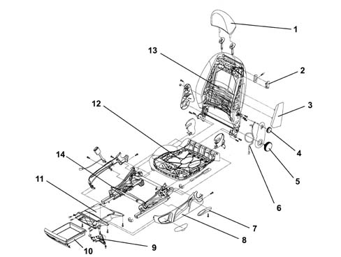
1- Head restraint
2 - Backrest release
3 - Side Air Bag
4 - Lumbar adjustment knob
5 - Backrest adjustment knob
6 - Air Bag cable
7 - Cushion height adjustment lever
8 - Carrier
9 - Connector carrier bracket
10 - Glove compartment
11 - Glove compartment console
12 - Cushion spring cables
13 - Seat lumbar adjustment
14 - Seat raising assembly
FRONT SEATS
There is a special structure in the front section of the front seats designed to prevent the body of the occupant from sliding forwards under their seat belt in the case of a violent frontal impact.
This helps in limiting injuries to the abdomen and the femur as it reduces the forward acceleration of the occupant's body.
The Air Bag module, seat belt fastened sensor and heat pad (if present) connectors are secured a connector bracket, anchored in turn to the seat structure. The bracket (9) may be rotated forward by means of the anchorage clip to gain access to the connectors.
The seats are fitted with an efficient suspension system with a flexible system using thin steel wires (12) covered in plastic and secured to the perimeter frame through springs.
There is a modern support system (13) in the seat for the lumbar region, to help support the driver's back, which has been specially designed to ensure comfort and support. The backrest is adjusted using a special knob, located on the backrest, which alters the supports (4).
The front head restraints (1) are fitted with a height adjustment device (two positions). In the case of an impact the head restraint is further forwards to adapt the distance between the head and the backrest and there is also a rocker device which reduces the risk of whiplash.
The driver's seat cushion can be height adjusted, with a vertical travel of 48 mm. The height is adjusted using a ratchet lever (7) with greatly reduced loads.
The backrest angle is adjusted by turning a rubber-covered knob (5), which gives precise adjustments.
REAR SEATS
There are two different versions:
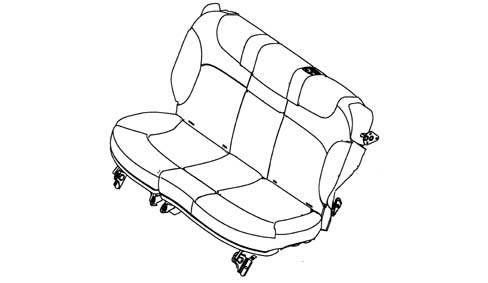
- classic rear seats where the backrests and cushions can be folded over
- sliding rear seats with a rocker adjustment of the backrests in two positions (the backrests only and not the cushions can be folded over).
The diagram below illustrates classic seats
REAR SEATS
The diagram below illustrates sliding seats
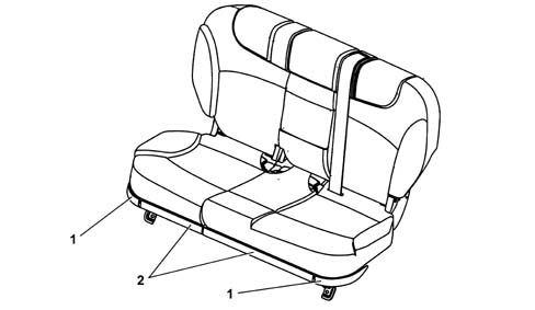
1 - left/right backrest folding levers
2 - left/right backrest adjustment levers
REAR SEATS
Both are fitted with a steel partition and are divided into two sections (40/60) which operate independently both in terms of folding over and the sliding adjustment. Featuring a head protection system the rear seats are also fitted with three head restraints which can be adjusted for angle and heght (one position only).
There is also a version where the cushions can be raised using a special mechanism making it possible for children to wear the seat belts in the correct position.
The bodyshell's torsional and bending rigidity properties give the car good passive strength qualities, excellent driving comfort and precise steering that is comparable to the best vehicles in its class.
| TORSIONAL RIGIDITY | DaNm / rad |
|---|---|
| Unadorned body + windscreen (3 door version) | 121600 |
| Unadorned body + windscreen (5 door version) | 92800 |
| BENDING RIGIDITY | DaNm / mm |
| Unadorned body + windscreen (3 door version) | 1100 |
| Unadorned body + windscreen (5 door version) | 910 |
The high rigidity levels bring many advantages:
- lower vibrations;
- lower noise;
- increased resistance to failure caused by the use of the vehicle over particularly uneven roads;
IMPACT DAMAGE AND REPAIRS
Special attention has been paid to the structure of the vehicle during impact tests at low speed to limiting the deformation of the passenger compartment, safety and repair costs.
The vehicle has a special feature behind the front bumpers, a robust crossmember made from a high-resistance material which can absorb all the energy from a typical impact at low speed which prevents damaging the most expensive components located inside the engine compartment. The crossmember is bolted onto both the front side members, to facilitate removing and refitting operations, and to a modular structure known as the front-end which is composed of the following modules:
- Air duct
- Carrier on which the headlamps and other electrical components are fitted
air conditioning module
The Front-End can be replaced in one piece (if the accident has involved the entire front of the vehicle) or the various modules can be replaced separately (typical situation where parts not affected are removed).
In both cases the time involved and consequently the labour costs are considerably reduced compared with conventional fittings. The vehicle also has a collapsible system for fastening the front light clusters to the front-end which retracts after an impact so that they are not damaged. To repair the vehicle simply tighten the new fastening tabs on the light casing.
The rear of the vehicle has similar features to the front:
- there is also a rigid high-resistance material crossmember that houses high-efficiency energy-absorbers by the rear side members.
- in this case, however, the energy-absorbing elements are the only components that need replacing in the case of shunts at low speed.
The particular layout and strength of the centre section of the crossmember also ensures limited damage in the case of typical impacts whilst reversing into trees or lampposts.
View of assembly
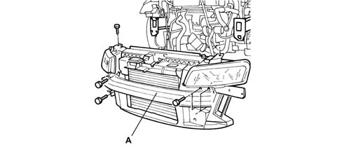
A - Front End
GERMAN MARKET INSURANCE CLASSIFICATION
The features described above have made it possible for the vehicle to gain class 12 status in the German insurance classification system, designed to be adopted shortly in other European countries. A class is allocated according to the repair costs of the vehicle following two standardized laboratory impacts according to the accident frequency for a given model (or the model replaced for new vehicles).
The lower the class, the less the premium paid by the customer for KASKO insurance for their vehicle.
Class 12 for the basic model means that it is amongst the best vehicles in its segment in terms of insurance costs in Germany.
The insurance class in Germany and in England at the launch was determined through the analysis of low speed (15 km/h) laboratory impacts.
These types of impacts are regulated in accordance with standards N. S-2055 for front impacts and N. S-2056 for rear impacts.
ENGLISH MARKET INSURANCE CLASSIFICATION
Similarly to the German market, the association of English insurers classify each new model according to the repair costs following two standard laboratory impacts and on the basis of the level of security against total or partial theft. With these criteria in mind the vehicle is at the top of its class thanks to the large number of devices, both electronic and mechanical, and technical features which make it almost untouchable.
FIRE SAFETY
The entire vehicle, from the bodyshell to the various components, has been subject to the most recent and stringent FIAT fire safety regulations and features the following measures:
- The underbody fuel and anti-evaporation pipes are arranged in parallel to the underfloor side member.
- Sections of metal pipe have been used in the engine compartment (in the right corner) to prevent fuel leaks if they are struck during an accident.
- The adoption of a returnless fuel system (petrol engines only) makes it possible to eliminate the fuel return pipe to the tank thereby reducing the risk of leaks.
- The FPS (Fire Prevention System) inertia switch allows the engine to be switched off immediately a few tenths of a second after the beginning of an impact.
- The plastic tank (a material that prevents the risk of an explosion) conforms to future directives and is located in an area where it is protected if there is a collision and is capable of resisting deformation without the risk of leaks.
- The transverse position of the battery inside a plastic drip tray reduces the risk of contact between the positive terminal and other bodyshell metal components in the case of a front impact.
- All the cables are electrically insulated and housed inside corrugated casings for mechanical protection against the risk of abrasion.
- The electrical insulation of the starter motor/battery power lead is made from APC (which is highly resistant to abrasion and cutting) and the cable routing has special fastenings.
- All the components that could be affected by heat (reduced by a special shield) given off by the catalyzer are located a suitable distance away.
- Large metal shields have been fitted to the entire underbody guaranteeing the protection of the components where heat is given off by the exhaust pipe (tank, handbrake cables, flexible supports).
INTRODUCTION
The safety offered by the vehicle stems from a combination of the design of the structural components, the large number of special devices that make up the system for protecting the occupants and the attention paid to the design of the vehicle interior and exterior components.
STRUCTURE
The new Stilo chassis is composed of two longitudinal elements that support the vehicle along its entire length and are connected to one another by transverse elements. The actual bodyshell is positioned on the frame produced in this way.
Energy absorption in a front or rear impact is mainly transferred to the two lines constituted by the front struts, rear struts and underfloor side members. The continuity of these three parts for the entire length of the vehicle guarantees gradual deformation depending on the seriousness of the impact. The high-resistance material with different thicknesses and strengths is designed to withstand the forces produced by the front and rear crossmembers during low speed impacts without damage and, at the same time, allowing all the energy produced during high speed impact to be absorbed without deforming the passenger compartment.
There are two further small struts, above the engine, in front of the H nodes, which, when deformed, stop the stresses reaching the upper part of the vehicle, especially when the vehicle is involved in an impact with the rear of a lorry.
BODYWORK
The outer bodyshell, also mainly constructed from highly resistant materials, withstands the forces produced by the centre side members in longitudinal impacts whilst playing an important role in side impacts.
It features a wide section for the side members and the centre pillars and box sections in the roof and a crossmeber connecting the two centre pillars.
The vehicle bodyshell is constructed entirely from panels galvanized on both sides.
This includes all the bodyshell components, from the floor to the roof, the side panels, the doors and every interior and exterior bodywork element.
The majority of the elements are the standard zinc thickness (8μm), whilst all the safety elements, such as, for example, the struts and side members and the housings for the front and rear suspension mountings have a zinc coating of 20 μm
Bonnet
New safety features have been introduced. These incluce preset collapse lines that, together with special retaining hooks, prevent the bonnet going through the windscreen in the case of impact.
Underdashboard crossmember
The magnesium crossmember located between the two front pillars under the dashboard follows the entire upper dashboard and ensures a strong connection between both the pillars and the floor to which it is connected by two small struts. This structure makes a considerable contribution to deformation properties of the entire front area of the passenger compartment in both front and side impacts. In addition, acting as a support structure for the steering column, it prevents the possibility of the steering wheel moving backwards or lifting up in all types of front impacts.
Luggage compartment
The luggage compartment has been designed taking into account the different objectives for 3 and 5 door versions.
On the 5 door version the aim is to offer the customer a spacious luggage compartment suitable for the needs of a family.
the design of the vehicle has produced a luggage compartment with a capacity of 350 litres.
On the three door version the luggage compartment has a capacity of 300 litres which is ample for a large amount of luggage.
Bumpers
These are designed to protect the car optimally against minor bumps. The crossmembers located just behind the outer shell of both bumpers ensure that there is no damage from impacts at up to 4 km/h
The projecting trim prevents the abrasion of the main body paintwork.
COSMETIC ANTI-CORROSION WARRANTY
The vehicle bodyshell is made from panels 100% galvanized on both sides.
This therefore includes all the bodyshell components, from the floor to the roof, the side panels, the doors and all the interior and exterior bodywork elements.
The majority of the elements are the standard zinc thickness (8m), whilst all the safety elements, such as, for example, the struts and side members and the housings for the front and rear suspension mountings have a zinc coating of 20 m.
In conjunction with the total galvanizing of the panels and the protection package offered by the polishing and painting processes, protective wax is also applied to these components and to the moving parts (bonnet, doors, tailgate).
This material is applied by high tension spraying through a special automatic process following the paint spraying and covers the inside of the box sections with a water-repellant, anti-corrosion protective film that even penetrates the panel joins and forms an extremely effective barrier against the main sources of corrosion, i.e. the aggressive solutions coming, from example, from the salt on the roads.
The total galvanizing of the bodyshell, together with the protection package afforded by the painting process allows a three year cosmetic anti-corrosion warranty to be offered.
The protective package consisting of galvanized panels, cataphoresis and protective wax applied to the internal structures makes it possible for the panels to last 12 years without perforation in the harshest climates in Central and Northern Europe.
Parts & tools for this job For 2001 Fiat Stilo
- TOOLTrim removal tool kitSearch: trim removal tool kit
- PARTTouch-up paintSearch: Fiat touch up paint
- PARTPanel clip assortmentSearch: Fiat panel clips assortment
Links open Amazon search results in a new tab. As an Amazon Associate I earn from qualifying purchases.