
Introduction - GEARBOX
- Make
- Fiat
- Model
- Stilo Factory Service Manual
- Year
- 2001–2007
- Section
- General › Introduction - GEARBOX
Introduction - GEARBOX
The following gearboxes are available for the Stilo
- C514 6 speed for the 1.2 16V version
- C514R 5 speed (R stands for 'reinforced') for the 1.6 16V version
- C510 5 speed for the 1.8 16V version
- C510 5 speed for the 1.9 JTD 80 bhp version
- C530 5 speed with selespeed electrohydraulic unit for the 2.4 20V version
- Getrag 5 speed for the 1.9 JTD 115 bhp version.
Manual gearbox external linkage
The external linkage ensures slick, noiseless manoeuvres.
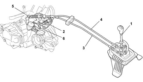
1 - Gearbox control lever
2 - Support for gear selector and engagement cables
3 - Gear engagement cable
4 - Gear selector cable
5 - Gear engagement lever
6 - Selector lever on gearbox
Construction features
The structure of the gearbox consists of:
- a gearbox casing which contains and supports the main and layshafts, rods and gear selector forks and the gear selector and engagement device.
- a rear cover which contains the 5 speed gears and the rear bearing retaining plate for the main and layshafts (on the C.514.6 gearbox it also contains the 6 speed gears);
- a bell housing which contains the clutch and the thrust bearing.
Main shaft
The main shaft consists of:
- 1st, 2nd speed and Reverse gears fitted directly on the shaft
- 3rd, 4th and 5th speed gears (and 6th for the C514.6 gearbox) fitted on the shaft.
The main shaft is supported:
- by means of two ball bearings for the C510 gearbox
- a front roller bearing and a rear ball bearing are present on the C514 gearbox
- two high-precision taper roller bearings on the C530
Layshaft
The layshaft consists of:
- for the C510 and C514 gearboxes, 1st, 2nd, 3rd, 4th, 5th (and 6th) speed gears fitted on the shaft.
- for the C530 gearbox, 1st and 2nd speed gears fitted on needle bearings with synchronisers, and 3rd, 4th and 5th speed gears fitted to the shaft.
The layshaft is supported on:
- a front foller bearing and a rear ball bearing for the C510 and C514 gearboxes,
- two high-precision taper roller bearings for the C530 gearbox
Gears
For all gearboxes, gears are of the following type:
- helical toothed for the forward speeds
- straight toothed for reverse.
synchronisers
The synchronizers for the forward speeds are the Borg-Warner type.
For the C510 and C514 gearboxes, the arrangement for the synchronizers is the split type because the synchronizers for the 1st and 2nd speeds are fitted on the layshaft, whilst those for the 3rd, 4th, 5th (and 6th) speeds are on the main shaft.
This solution reduces gearbox noise in neutral because the 3rd and 5th (or 6th) gear seats are not driven.
In addition, the engagement and synchronization loads are reduced as a result of the corresponding reduction in the inert masses rotating downstream of the crankshaft.
On the C530 gearbox, the synchronisers are triple cone for 1st and 2nd speed, double cone for the 3rd speed and single cone for the 4th and 5th.
Differential
The differential unit is located in the rear of the gearbox casing.
On the C510 and C514 gearboxes, this consists of:
- a crown wheel and pinion reduction
- a differential housing constructed in a single piece which includes the differential and planet gears.
On the C530 gearbox this consists of:
- a crown wheel and pinion reduction
- a differential housing made from two half casings which include the planet and satellite gears.
The differential is supported by two conical roller bearings.
- The planet gears have a splined profile with which the two flanged couplings connected to the two driveshafts which transmit the power to the wheels mesh.
C514 gearbox - 5 speed
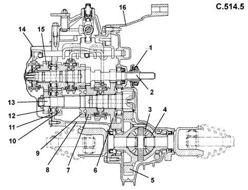
1 - Thrust bearing
2 - Main shaft
3 - Planet gears
4 - Differential gears
5 - Ring gear
6 - 1st speed driven gear
7 - 2nd speed driven gear
8 - Gearbox casing
9 - 3rd speed driven gear
10 - 4th speed driven gear
11 - Rear bearing retaining plate
12 - 5th speed driven gear
13 - Layshaft
14 - Rear cover
15 - 5th speed drive gear
16 - Bell housing
Differential
C514 6 speed gearbox
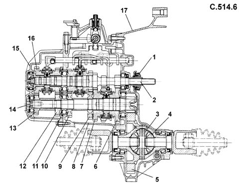
1 - Thrust bearing
2 - Main shaft
3 - Planet gears
4 - Differential gears
5 - Ring gear
6 - 1st speed driven gear
7 - 2nd speed driven gear
8 - Gearbox casing
9 - 3rd speed driven gear
10 - 4th speed driven gear
11 - Rear bearing retaining plate
12 - 5th speed driven gear
13 - 6th speed driven gear
14 - Layshaft
15 - Rear cover
16 - 6th speed drive gear
17 - Bell housing
Differential
C510 gearbox
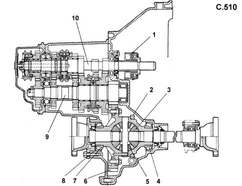
1 - Thrust bearing
2 - Speedometer gear
3 - Differential gears
4 - Taper roller bearing
5 - Planet gears
6 - Ring gear
7 - Taper roller bearing
8 - Differential housing bearing adjustment shim
9 - Layshaft
10 - Main shaft
Differential
Gearbox C530
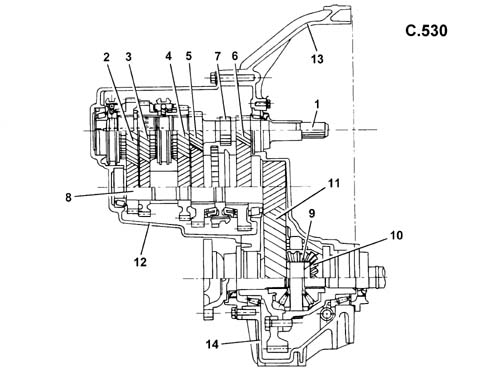
1 - Main shaft
2 - 5th speed drive gear
3 - 4th speed drive gear
4 - 3rd speed drive gear
5 - 2nd speed drive gear
6 - 1st speed drive gear
7 - Reverse speed drive gear
8 - Layshaft
9 - Satellite gears
10 - Planet gears
11 - Ring gear
12 - Gearbox casing
13 - Clutch casing
14 - Differential support housing
Differential
Getrag Gearbox
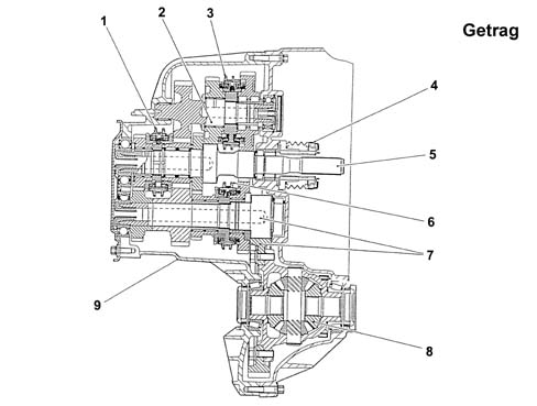
1 - 3rd/4th speed synchroniser
2 - Intermediate shaft
3 - 1st/2nd speed double-cone synchroniser
4 - thrust bearing
5 - mainshaft
6 - 5th/reverse synchroniser
7 - crown wheel/pinion
9 - differential
10 - gear casing
CONSTRUCTION FEATURES
Gearbox C530
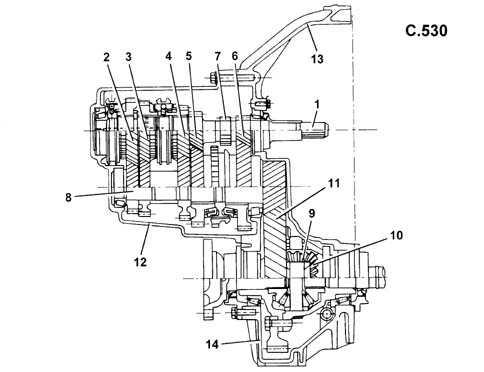
1 - Main shaft
2 - 5th speed drive gear
3 - 4th speed drive gear
4 - 3rd speed drive gear
5 - 2nd speed drive gear
6 - 1st speed drive gear
7 - Reverse speed drive gear
8 - Layshaft
9 - Satellite gears
10 - Planet gears
11 - Ring gear
12 - Gearbox casing
13 - Clutch casing
14 - Differential support housing
CONSTRUCTION FEATURES
The Stilo 2.4 petrol version is fitted with a C530 manual gearbox with a Selespeed electrohydraulic unit.
The clutch and gearbox controls are automated by means of a hydraulic servo system governed by a special electronic gearbox in constant communication (via a CAN line) with the engine control unit.
This system allows the clutch pedal to be eliminated.
COAXIAL HYDRAULIC OPERATION (CSC)
The CSC hydraulic system is known as coaxial because it consists of an aluminium actuator cylinder, located in the bellhousing, which is coaxial to the clutch and the main shaft.
Thanks to the elimination of external components (selector fork, shaft, release lever) this type of system, which incorporates the hydraulic actuator with the thrust bearing, guarantees improved performance throughout the working life of the vehicle and excellent insulation of the noise and vibrations coming from the power unit.
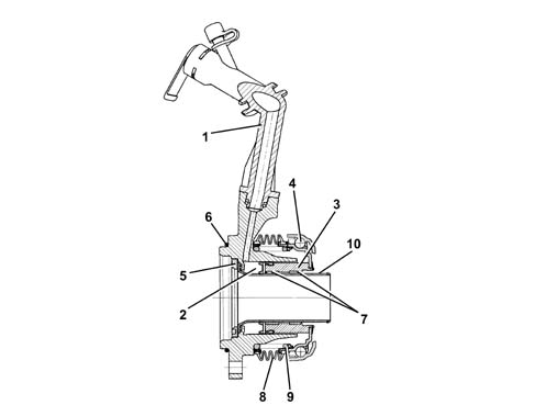
1 - Fluid inlet pipe
2 - Expansion chamber
3 - Piston
4 - Thrust bearing
5 - Oil seal
6 - O-ring
7 - Anti-wear pads
8 - Rubber mounting
9 - Spring
10 - Guide pipe
DESCRIPTION OF THE SELESPEED SYSTEM
The following components produce the power-assistance for the clutch and the gearbox control:
- hydraulic supply unit,
- actuator assembly,
- gearbox electronic control unit,
- specific sensors,
- joint sensors.
HYDRAULIC SUPPLY UNIT
The function of this sub-system is to provide the energy required to move the clutch and gearbox linkage (activated by the driver on a regular version) in a pressure range of between 40 and 60 bar and it consists of:
- hydraulic reservoir (0.5 l)
- electric pump (hydraulic geared pump linked to the commutator type electric motor)
- connecting pipes and connectors.

1 - hydraulic accumulator
2 - even gears engagement solenoid valve
3 - odd gears engagement solenoid valve
4 - clutch engagement/release solenoid valve
5 - brake solenoid valve
6 - oil pressure sensor
ACTUATOR ASSEMBLY
The function of the actuator assembly is to activate the clutch and the internal gearbox controls in order to carry out the gear change stage.
The actuator assembly consists of:
- Gear control: this replaces the traditional gear control and allows the operation of the gear linkage in order to implement the gear shift. It includes:
- Valve Assembly: this contains all the proportional solenoid valves and the system hydraulic accumulator.
- CSC: this is the hydraulic actuator that allows the engagement and release of the clutch.
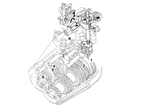
GEARBOX ELECTRONIC CONTROL UNIT
Technologically similar to the engine management control unit, it is located in the passenger compartment.
Like all electronic control units it has the task of processing the driver's requests, transforming them into inputs for all the commands needed to satisfy these requests. In order to carry out its tasks the control unit makes use of the information from the High Speed CAN and information from the sensors and potentiometers in specific locations which provide constant information on the operating state.
The control unit communicates with the injection control unit through a CAN line and is fitted with a tester line.
The following information required for control system operation is taken from the CAN network:
- accelerator pedal position
- engine speed
- vehicle speed
- engine torque.
- brake status (ON/OFF)
The further information that the system uses is provided by specific sensors and potentiometers (which are part of the system) and by joint sensors and potentiometers which are shared with other electronic systems present on the vehicle.
SPECIFIC SENSORS:
- Gearbox input shaft speed sensor
- actuator position detection potentiometers
- analogue sensor for detecting hydraulic pressure
JOINT SENSORS:
- engine rpm sensor
- gearbox output speed sensor
- brake pedal switch
- door open switch
Each of the components described above is involved each time there is an input via the following controls:
- UP control on the steering wheel,
- DOWN control on the steering wheel,
- controls on the lever on the tunnel (Joystick)
- AUTO control.
The gear selector control is implemented through special switches located on the steering wheel or the lever on the centre console in place of the conventional control.
STEERING WHEEL CONTROLS
The steering wheel houses 2 control levers:
- UP control on the right side,
- DOWN control on the left side.
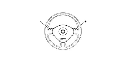
STEERING WHEEL CONTROLS
UP CONTROL ON THE STEERING WHEEL (right side identified by '+')
Gears can be engaged sequentially during acceleration by operating the 'UP control.
DOWN CONTROL ON THE STEERING WHEEL (left side identified by '-').
Gears can be engaged sequentially during deceleration by operating the 'DOWN control (shifting down).
CONTROLS ON THE LEVER ON THE TUNNEL (JOYSTICK)
The 'UP and 'DOWN controls are replicated by a special lever on the tunnel. This can only move in the direction of motion to engage gears during acceleration ('UP); to the rear of the car to engage gears during deceleration ('DOWN).
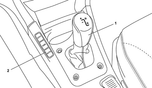
1 - Gear control lever (joystick_
2 - AUTO button
AUTO CONTROL
In addition to the above controls, the system also offers an automatic gear shift mode. This is achieved by activating the AUTO control on the tunnel console near the gear control lever.
The AUTO function is unlike a normal automatic transmission in that it offers a single driving strategy suited to town use or very busy routes (for example driving in traffic in 'stop and go' conditions and/or frequent deceleration and acceleration) requiring frequent gear changes.
CONTROL PANEL DISPLAYS
The control panel displays relate to:
- speed engaged,
- possible auto operation,
- system failure.
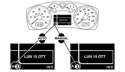
CONTROL PANEL DISPLAYS
The switch from MANUAL to AUTO can only take place with the engine running using the button at the side of the lever (joystick).
The mode selected remains memorized when the engine is switched off.
When the Cruise Control is switched on, the system automatically moves to Auto mode.
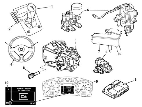
COMPOSITION
The Selespeed system components are as follows:
- gear selector lever on the tunnel (1)
- AUTO button (2)
- Selespeed control unit (3)
- gear selector buttons on steering wheel (4)
- solenoid valve unit/actuator assembly (5)
- electric pump (6)
- hydraulic fluid reservoir (7)
- gearbox speed sensor (8)
- gear selection display (9)
- robotized gearbox fault signal (10)
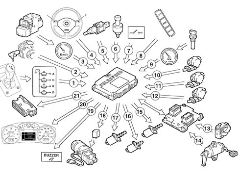
MAIN SYSTEM INTERFACE COMPONENTS
Gear selector lever switch (1)
Engine rpm sensor (CAN line from engine management control unit) (2)
Vehicle speed (from A.B.S. control unit via CAN line) (3)
Gear change buttons (4)
Brake pedal switch (5)
Oil pressure sensor (6)
Driver's door switch (7)
AUTO mode button (8)
Gearbox input rpm sensor (9)
Clutch position sensor (10)
Gear selector position sensor (11)
Gear engagement position sensor (12)
Throttle body integral with D.V.E. (13)
Accelerator pedal potentiometer (CAN line from engine management control unit) (14)
Proportional pressure solenoid valves (2) (15)
On-off solenoid valve (1) (16)
Proportional flow solenoid valves (17)
Electric pump (18)
Buzzer (19)
Control panel (20)
Diagnostic socket (21)
Starter enablement relay (22)
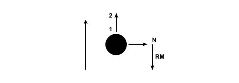
OPERATIONS TO BE CARRIED OUT FOR STARTING/DRIVING VEHICLE
Stage 1: starting
1) Press the brake pedal,
2) Start up the vehicle,
3) Engage the gear (1st, 2nd or Reverse) for setting off (with the brake pedal pressed), using the lever (when setting off the control on the steering wheel is not received).
With the vehicle stationary and the engine running it is possible to engage 1st gear, 2nd gear or Reverse. The control simply requires an input to engage the gears and then it returns to its central position.
OPERATIONS TO BE CARRIED OUT FOR STARTING/DRIVING VEHICLE
Stage 1: driving
4) take your foot off the brake pedal and accelerate,
5) then operate the controls (on the lever or the steering wheel)
It is advisable to operate the accelerator control through gentle movements in the exactly the same way as for a traditional manual gearbox.
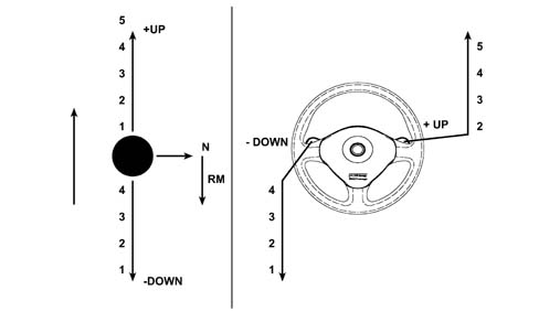
OPERATIONS TO BE CARRIED OUT FOR STARTING/DRIVING VEHICLE
6) The AUTO control is located on the tunnel, near the gear lever and allows the activation of the automatic gear change function.
The lever control takes priority if simultaneous requests are made using both the steering wheel buttons and the lever. A gear change request is NOT accepted with the car in motion if the request leads to rpm levels that are too high or too low. With the car at a standstill (or virtually still), gear change requests are accepted only if the brake pedal is pressed (applies also to neutral). The steering wheel buttons are disabled when the vehicle speed is below 15 Km/h.
HORN
A buzzer warns the driver of the following:
- system faults
- improper use (e.g. clutch overheating)
- car safety (e.g. doors open)
INCORRECT OR INCONSISTENT DRIVER OPERATION
The Selespeed system prevents incorrect driver operation that could cause dangerous situations or be detrimental to the system.
The strategies are:
- the lever control takes priority if simultaneous requests are made using both the steering wheel buttons and the lever.
- reverse gear cannot be engaged with the vehicle moving,
- a gear change request is not accepted with the car in motion if the request leads to rpm levels that are too high or too low.
- only 1st gear, 2nd gear and Reverse gear can be engaged with the vehicle stationary and the engine running.
The system has been designed taking into account the possibility that incorrect manoeuvres that could create dangerous situations could be requested allowing:
- the engine can only be started with a gear engaged if the vehicle is stationary, the accelerator pedal released and the brake pedal pressed (the system initially places the gearbox in automatic neutral and then enables the starting of the engine),
- with the car at a standstill (or virtually still), gear change requests are accepted only if the brake pedal is pressed (applies also to neutral). This prevents dangerous situations in case the lever/buttons on the steering wheel are accidentally operated by someone else or even by the driver,
- disabling of the steering wheel buttons at vehicle speeds of less than 15 km/h, thereby preventing possible driver error during parking manoeuvres,
- inhibition of the 'neutral' control above a preset speed, thereby preventing incorrect operation in critical situations, for example, downhill
- AUTO mode cancellation when the driver selects the gear directly using the lever/buttons, the driver's selection takes priority in this situation.
- automatic engagement of neutral and buzzer warning the driver for a limited period in the following cases: insufficient oil pressure for the management of the clutch, engine started and door open (starting with the door open is, however permissible because the driver's action on the brake or the accelerator is detected), engine started with gear engaged and no sign of operation of accelerator or brake for more than 5 secs., gear engaged and accelerator released and brake pedal pressed for at least 30 secs.
- independent gear change if the driver insists outside of the rev range without changing gear.
TURNING ON THE SYSTEM
This takes place by turning the ignition key. The system informs the driver, through the instrument display, of the gear engaged and, after 1 - 2 secs., the system is capable of accepting new gear changes from the lever only.
WITH THE ENGINE SWITCHED OFF
Any gear whatsover can be engaged (including Reverse) and neutral can be engaged; these operations can only be carried out with the brake pedal depressed.
ENGINE START-UP
The system only enables the starting enablement relay if the gearbox is in neutral which the system automatically does when the brake pedal is pressed at the time of starting.
VEHICLE TAKE OFF / ACCELERATION
Only 1st gear, 2nd gear or Reverse can be engaged for take off after starting. For safety reasons 1st and 2nd gears can only be engaged with the brake pedal pressed, whilst for Reverse gear in addition to this condition the vehicle must also be at a complete standstill.
When the brake pedal is released and the accelerator pedal operated, the system gradually closes the clutch and allows the vehicle to take off.
Modulating the position of the accelerator pedal allows the system to meter the torque transmitted by the clutch and consequently the acceleration of the vehicle.
When the system detects synchronism between the engine and clutch speeds, it closes the clutch completely
VEHICLE SLOWING DOWN
When the accelerator is released the system recognizes the intention to slow the vehicle down and automatically reopens the clutch to prevent the engine from stalling.
This reopening takes place at an engine speed that depends on the deceleration and the controls implemented by the driver (brake pressed or not)
When slowing down, if the speed engaged is higher than 3rd, the system automtically shifts down.
When the vehicle stops, 1st gear is engaged automatically.
VEHICLE DOWNHILL
When the vehicle is driving downhill, a gear is engaged and the accelerator pedal is released, the speed increases, but as the preset speed in the control unit is reached, the clutch is automatically closed again to provide an engine braking effect; if the accelerator is pressed again, the driver resumes control of the vehicle.
GEAR SHIFT
With the vehicle moving and the clutch completely closed, the system is capable of accepting gear shift commandsif they are compatible with the rpm range.
Gear shifts can be implemented, as described previously, using the controls on the steering wheel or the lever (joystick) on the tunnel (if the lever and the steering wheel control are operated simultaneously, the lever takes priority).
Once a gear shift request has been accepted, the shift is carried out according to an automatic sequence that reflects actual driver behaviour:
- engine torque reduction through a command from the Selespeed control system to the engine control system with the simultaneous opening of the clutch,
- release, selection and engagement of the new gear (parallel to this stage the engine is controlled so that the speed for the clutch after the engagement of the new gear can be reached),
- modulated clutch closure and simultaneous gradual return to maximum possible torque delivery by the engine. When the system detects synchronism between the engine and clutch speeds, the clutch is completely closed,
- a gear shift in progress may be interrupted at any time by a new request provided that it is compatible with the engine rpm range.
- the actuator control sequences during a gear shift are accompanied by waiting, allowing the repetition of the control if the outcome is not correct the first time, engaging a higher gear than requested.
AUTOMATIC GEAR SHIFT (AUTO MODE)
The Selespeed system has an automatic operating mode, similar to the one on conventional automatic transmissions.
The selection of the speed to engage is made using a (single) map that correlates the position of the accelerator pedal, the vehicle speed and the optimum gear.
If the accelerator pedal is released, the system keeps the clutch as closed as possible to allow maximum engine braking.
Gears are shifted in exactly the same way as during semiautomatic operation. The same transmission and engine control parameters are used.
REQUEST TO SHIFT TO NEUTRAL
With the engine off the brake pedal must be pressed, as described previously.
With the vehicle moving, this request is not accepted above a preset vehicle speed.
SWITCHING OFF THE ENGINE AND THE SYSTEM
With the ignition key in the OFF position, the engine switches off and the Selespeed system keeps the gear selected engaged. The Selespeed system is only completely deactivated after having received a 'nil speed' input from the engine, gearbox input, gearbox output and after having saved the functional and diagnostic data in the control unit stable memory (all of this takes place in less than 2 seconds).
INFORMATION FOR THE DRIVER
The information for the driver concerning the operation of the Selespeed system is transmitted through a display located in the centre of the instrument that indicates the gear engaged or the AUTO mode or the failure of the system; a buzzer signals the improper use of the vehicle, or an unsafe situation or the failure of the system (e.g. improper use may be starting with the clutch overheating, an unsafe situation could be leaving the vehicle not in gear).
Push-starting
The car can be push-started as follows:
- turn the ignition key to the ON position
- check the warning light has gone off (after 10 seconds);
- with the car running at a certain speed and the gearbox in neutral, shift up a gear (+) using the selection lever.
This operation cannot be carried out if the battery is completely flat.
Checking transmission fluid level
The Selespeed system fluid level should be checked with the vehicle on a flat surface and the engine switched off and cold.
Proceed as follows to check the level:
- turn the ignition key to the ON position
- check the oil level at the references (MIN and MAX) on the hydraulic fluid reservoir. The correct level is between the two marks.
- if the level is below the MAX mark, add fluid (C.S. Speed Tutela) until the level is correct.
- after having complete the top up, turn the ignition OFF.
Specifications
The Stilo version with a 1910 jtd engine is fitted with a new generation Getrag gearbox coded: C538.
Main gearbox features are as follows:
- takes up less room at either side
- excellent manoeuvrability at all speeds
- very low noise levels
Gearbox configuration is transverse with 3 shafts and an internal differential. All gears come with HRC teeth that are superfinished after heat treatment.
Gearbox and clutch housings are computer-modeled (FEM/FINITE ELEMENT METHOD) to achieve the lowest weight without affecting strength.
The gears are all synchronised, including reverse, and synchroniser rings are all brass Borg Warner type.
First and second gears, including synchroniser rings, are fitted to an idler shaft between the main and layshafts.
The synchroniser gear set for third and fourth speeds is fitted on the mainshaft while the fifth speed and reverse sets are on the layshaft.
The synchroniser rings on the most frequently used gears, i.e. the first and second speeds, are double done to ensure lower engagement effort than with a conventional synchroniser or one with a single ring.
The interal gear control system is designed over three selection planes, with a central gear positioner mounted on bearings.
The clutch control is hydraulic with a coaxial CSC system coaxial on the mainshaft inside the gearbox.
The gears and drive chains inside the gearbox are lubricated dynamically by channeling oil flows through holes in the casings and on the mainshaft and layshaft and also through additional plastic channels; all this allows improved torque transmission efficiency and more effective wear prevention. This system has a clutch plate wear recovery device that allows the force on the clutch pedal to be kept constant during the working life of the vehicle.
The advantages of this system are as follows:
- improved acoustic comfort,
- reduced shift effort
- lever free of vibration and shudder
First speed
The drive entering from the main shaft is transmitted to the intermediate shaft through the synchro engagement and the 1st speed gear (on the intermediate shaft).
The 3rd speed gear (on the main shaft and currently in 'neutral') allows the transmission of the drive from the intermediate shaft to the layshaft and then to the differential, thereby completely the kinematic chain for first speed.
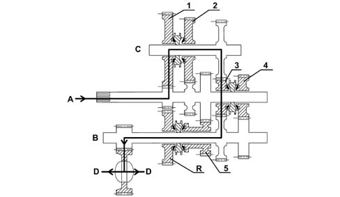
A - main shaft input
B - layshaft
C - intermediate shaft
D - differential output
Second speed
The drive entering from the main shaft, is transmitted to the intermediate shaft via the synchro engagment and 2nd speed gear (on the intermediate shaft).
The 3rd speed gear (on the main shaft and currently in 'neutral') allows the transmission of the drive from the intermediate shaft to the layshaft and then to the differential, thereby completing the kinematic chain for second speed.
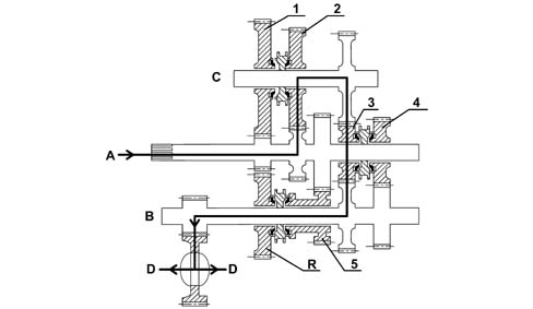
A - main shaft input
B - layshaft
C - intermediate shaft
D - differential output
Third speed
The drive entering from the main shaft is transmitted directly to the layshaft and then to the differential through the synchro engagement and 3rd speed gear (on the main shaft) producing the kinematic chain for third speed.
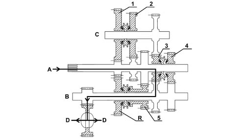
A - main shaft input
B - layshaft
C - intermediate shaft
D - differential output
Fourth speed
The drive entering from the main shaft is transmitted directly to the layshaft and then to the differential through the synchro engagement and 4th speed gear (on the main shaft) producing the kinematic chain for fourth speed.
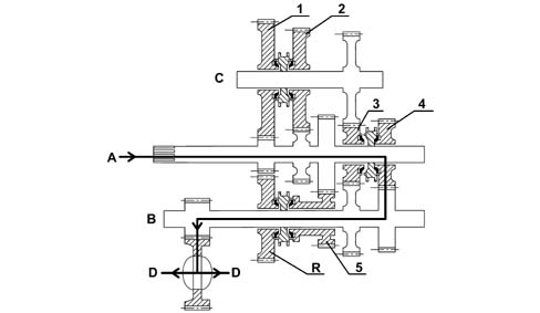
A - main shaft input
B - layshaft
C - intermediate shaft
D - differential output
Fifth speed
The drive entering from the main shaft is transmitted directly to the layshaft and then to the differential through the synchro engagement and 5th speed gear (on the layshaft) producing the kinematic chain for fifth speed.
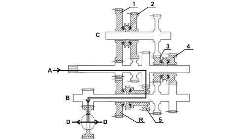
A - main shaft input
B - layshaft
C - intermediate shaft
D - differential output
Reverse gear
The drive entering from the main shaft is transmitted to the layshaft through the kinematic chain produced between the gear for 1st speed (on the intermediate shaft and currently in 'neutral') and reverse gear (on the layshaft) at the time the synchronizer is engaged.
In this configuration the drive is transmitted to the differential producing the kinematic chain for fifth speed.
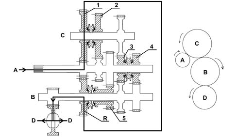
A - main shaft input
B - layshaft
C - intermediate shaft
D - differential output
Parts & tools for this job For 2001 Fiat Stilo
- TOOLTorque wrenchSearch: 3/8 inch torque wrench
- TOOLSocket setSearch: socket set metric
- BOOKHaynes manualSearch: Haynes manual Fiat Stilo
Links open Amazon search results in a new tab. As an Amazon Associate I earn from qualifying purchases.