| Installation Special Tool(s) | | Lifting Bracket, Engine 303-122 (21-068A) | | | Gauge Powertrain Alignment 502-003 (21-172) | General Equipment Materials Name Specification High-temperature grease ESD-M1C220-A Automatic transmission fluid ESP-M2C166-A Installation | | -
Move the selector lever into the "D" position. | | | -
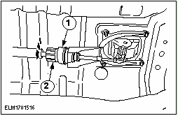
NOTE:The torque converter hub must engage fully in the oil pump drive gear. Check the installation depth of the torque converter. - Lay a Steel straightedge on the automatic transaxle flange.
- Check the installation depth between the transaxle flange and the torque converter centering spigot for the correct clearance: 2 mm.
| | | -
Apply a thin layer of High-temperature grease meeting Ford specification ESD-M1C220-A or equivalent to the centering spigot bore on the torque converter. | | | -
CAUTION:Make sure that the two locating tubes are installed. CAUTION:The torque converter must remain at the correct installation depth throughout the whole installation procedure. Check that the adapter plate is in correct position. Using the Floor crane bring the engine into installation position on the automatic transaxle and install the engine drive plate to the stud of the torque converter. | | | -
Screw in all flange bolts. | | | -
Install the lower flange bolts. | | | -
NOTE:Install the ground cable. Install the upper flange bolts. | | | -
Install the left-hand flange bolts. | | | -
Install the right-hand flange bolts. | | | -
Attach the torque converter to the engine drive plate (four nuts). - Install the plastic cover.
| | | -
Install the starter motor bracket and connector the starter motor. | | | -
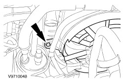
Install the oil level indicator tube. | | | -
Connect the turbine shaft speed (TSS) sensor electrical connector. | | | -
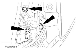
Connect the following electrical connectors. - Transmission range (TR) sensor
- Transmission control connector.
- Engine coolant temperature (ECT) sensor connector
- Clip the wiring harness in place.
| | | -
NOTE:The special tool is marked with an arrow and ``front''. Install the special tool. | | | -
NOTE:Correct position of the support insulator. Install the engine and transaxle assembly. | | | -
Loosen the nuts of the rear transaxle mount. | | | -
Screw the center bolt into the special tool and tighten it. | | | -
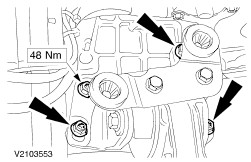
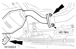
Install the rear transaxle mount to the side member. | | | -
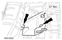
Install the upper front engine mount to the side member. | | | -
Tighten the nuts of the rear transaxle mount. | | | -
Install the center bolt into the right-hand support insulator. | | | -
Install the left-hand support insulator. - Center bolt.
- Nuts
| | | -
Install the compressor heat shield. | | | -
Install the accessory drive belt. - Left-hand stop.
- 3/8" square drive (ratchet).
- Push the belt tensioner as far as the left-hand stop using the square drive (ratchet) and install the accessory drive belt.
| | | -
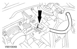
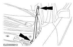
Install the coolant pipe. | | | -
Connect the heated oxygen sensor (HO2S) electrical connector. | | | -
Position the fan shroud assembly in the vehicle. | | | -
Attach condenser core to the radiator. | | | -
Connect the compressor electrical connector. | | | -
Attach the transaxle lower cooling line and the coolant hose to the radiator. | | | -
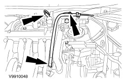
Install the transaxle cooling line. | | | -
Install the transaxle cooling line. | | | -
Connect and install the HO2S electrical connector. | | | -
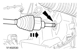
CAUTION:To avoid to damage halfshaft joints and boots, do not bend the inner halfshaft joint by more that 18 degrees the outer one by more that 45 degrees. NOTE:Do not damage the oil seal. Check that the snap-ring engages correctly. Install the left-hand front drive halfshaft. | | | -
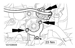
Install the intermediate shaft bearing bracket. | | | -
CAUTION:If an intermediate shaft bracket with two sets of holes (one set for CD4E application and one set for MTX application) is installed, take care to install the mounting bolts into the correct holes. CAUTION:To avoid damage to the halfshaft joints and boots, do not bend the inner halfshaft joint by more than 18 degrees, the outer one by not more than 45 degrees. Install the right-hand front drive halfshaft and the intermediate shaft bearing. | | | -
CAUTION:Do not damage boot and ABS sensor ring NOTE:Left-hand side shown, right-hand side similar. Install the suspension - Install the lower arm ball joint to the wheel knuckle.
- Install the tie-rod end.
- Install the stabilizer link rod to the strut.
- Attach the ABS wiring harness bracket to the strut.
| | | -
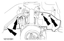
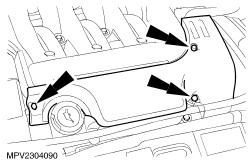
Install the right-hand fender splash shields. | | | -
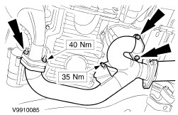
Install the dual converter Y-pipe. | | | -
Install the dual converter Y-pipe (cont.). | | | -
Connect and attach the HO2S electrical connector. | | | -
Install the fan to the radiator (one screw on each side). | | | -
Install the upper transaxle line tube. | | | -
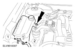
Install the coolant expansion tank. - Connect the coolant level sensor.
- Install the bolts.
| | | -
Connect the coolant expansion tank hoses. | | | -
Connect the powertrain control module (PCM) and attach the ground cable. | | | -
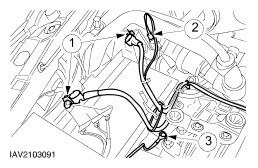
Connect the power steering lines. - Connect the connector.
- Connect the power steering lines.
- Install the bolt and the ground cable.
| | | -
Install the power steering fluid reservoir. | | | -
NOTE:New nuts do not need to be installed. Pre-tighten the nut on both suspension struts. | | | -
Tighten the nut on both suspension struts. | | | -
Connect the upper intake vacuum supply line and the heater control vacuum hoses. | | | -
Connect the evaporative emission (EVAP) hose. | | | -
Connect the suction accumulator electrical connector. | | | -
Attach the coolant hoses to the radiator and to the coolant passage. | | | -
Connect the heater hoses. | | | -
Connect the fuel lines and attach the safety clips. | | | -
Install the battery bracket. | | | -
NOTE:Install two ground cables together with one of the bracket screws. Install the battery bracket (continued). | | | -
Connect the fan motor electrical connectors. | | | -
Connect the cables. - Battery cable
- Connect the electrical connector.
- Ground cable
| | | -
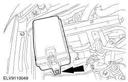
Install the central junction box (CJB). | | | -
Connect the bulkhead connector. - Connect the electrical connector.
- Connect the bulkhead connector and install the bolt.
| | | -
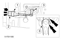
Install the selector cable. - Push the selector cable into the selector lever and clip it in place.
- Install the selector cable bracket.
| | | -
Remove the rear exhaust system heat shield. | | | -
Move the selector lever on the automatic transaxle into the ``D'' position and check the selector cable adjustment. - Hold the adjusting mechanism still.
- Open the selector cable lock.
- The markings on the selector lever must line up.
| | | -
Lock the selector cable in place. - Hold the adjusting mechanism still.
- Close the selector cable lock.
| | | -
Install the rear exhaust system heat shield. | | | -
Install the left-hand and right-hand front wheels. For additional information, refer to Section 204-04 Wheels and Tires. | | | -
Connect the accelerator and speed control cables. - Connect the cables.
- Clip the cables into the bracket.
| | | -
Install the water pump pulley cover. - Position the coolant hose in the clip and install the cover.
| | | -
Remove the auxiliary tool. | | | -
Install the air cleaner. For additional information, refer to Section 303-12B . | | | -
Coolant - fill the engine cooling system. For additional information, refer to Section 303-03 Engine Cooling. | | | -
NOTE:When the battery has been disconnected and reconnected, some abnormal drive symptoms may occur while the vehicle relearns its adaptive strategy. The vehicle may need to be driven 16 km (10 miles) or more to relearn the strategy. Finishing operations. - Check the routing of the vacuum hoses and wiring and secure them with Cable ties .
- Check the fluid level after the road test and correct as necessary.
- Check the engine and cooling system for leaks (visual inspection).
| | |