| Disassembly Special Tool(s) | | Remover, Vibration Damper, Crankshaft 303-338 (21-153B) | | | Installer, Vibration Damper, Crankshaft 303-130 (21-076) | | | Remover, Oil Seal, Crankshaft 303-293 (21-143) | | | Adapter for 303-338 303-338-02 (21-153A-02) | | | Remover, Oil Seal, Timing Cover 303-112 (21-051) | | | Socket, Spark Plug 303-499 (21-202) | | | Flange Holding Wrench, Universal 205-072 (15-030A) | General Equipment Disassembly | | -
Disconnect the exhaust gas recirculation (EGR) tube from the EGR valve. - Disconnect the hoses from the EGR tube to the differential pressure feedback EGR.
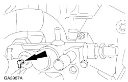
- Unscrew the tube fitting.
| | | -
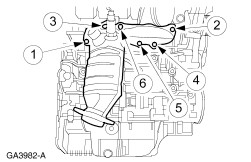
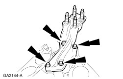
NOTE:Remove the nuts in the indicated sequence. Remove the RH exhaust manifold. | | | -
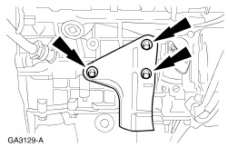
Remove the bolts and the connecting shaft bracket from the cylinder block. | | | -
Disconnect the generator electrical connections. - Remove the battery positive voltage retaining nut.
- Disconnect the voltage regulator electrical connector.
- Disconnect the stator circuit electrical connector.
| | | -
Disconnect the differential pressure feedback EGR electrical connector. | | | -
Disconnect the electronic vacuum regulator solenoid. | | | -
Disconnect the engine coolant temperature (ECT) sensor and remove the wiring harness. | | | -
Disconnect the intake manifold runner control (IMRC) cable. - Disconnect the IMRC cable from the retainer.
- Disconnect the IMRC cable end.
| | | -
Remove the IMRC. - Disconnect the IMRC electrical connector.
- Remove the IMRC bolts and the IMRC.
| | | -
Disconnect the six spark plug wires. | | | -
Remove the coil and ignition wires. - Disconnect the coil electrical connector.
- Remove the bolts and the coil.
| | | -
Remove the vacuum harness. - Disconnect the vacuum supply hoses from the upper intake manifold.
- Disconnect the EGR vacuum regulator solenoid vacuum hoses.
- Disconnect the fuel pressure regulator vacuum hoses.
- Disconnect the differential pressure feedback EGR vacuum hose.
- Disconnect the EGR valve vacuum hose and remove the vacuum harness.
| | | -
Disconnect the positive crankcase ventilation (PCV) hose from the throttle body. | | | -
Disconnect the throttle position (TP) sensor electrical connector. | | | -
Disconnect the idle air control (IAC) valve electrical connector. | | | -
NOTE:Remove the bolts in the indicated sequence. Remove the upper intake manifold. | | | -
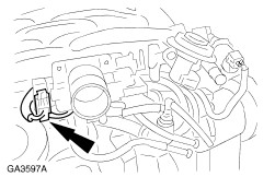
Disconnect the heated oxygen sensor (HO2S) electrical connector. | | | -
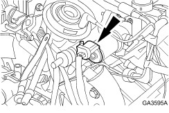
Disconnect the oil pressure switch electrical connector. | | | -
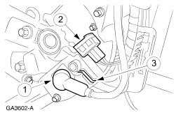
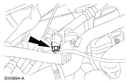
Disconnect the crankshaft position (CKP) sensor electrical connector. - Unclip the harness from the stud.
- Disconnect the electrical connector.
| | | -
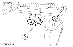
Disconnect the camshaft position (CMP) sensor electrical connector. - Unclip the harness from the stud.
- Disconnect the electrical connector.
| | | -
Disconnect the engine coolant temperature warning light electrical connector. | | | -
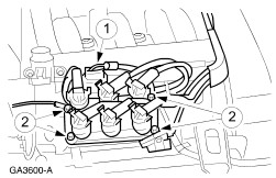
Disconnect the fuel injector electrical connectors and remove the wiring harness. | | | -
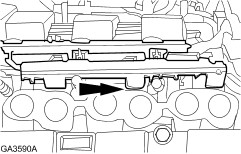
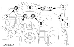
NOTE:Remove the bolts in the indicated sequence. Remove the lower intake manifold. | | | -
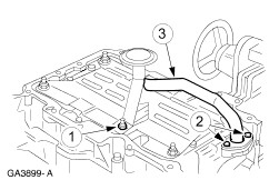
Disconnect the coolant hoses and remove the thermostat housing. | | | -
Disconnect the coolant distribution tube. | | | -
Remove the LH engine lifting eye. - Remove the nut.
- Remove the engine lifting eye.
| | | -
Remove the oil level indicator tube. | | | -
Remove the water pump drive belt. - Rotate the belt tensioner clockwise to relieve tension on the drive belt.
| | | -
Remove the PCV valve and hoses. - Remove the nut.
- Remove the PCV valve and hoses.
| | | -
Remove the water bypass. - Remove the bolts.
- Remove the water bypass.
| | | -
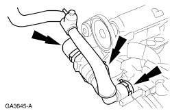
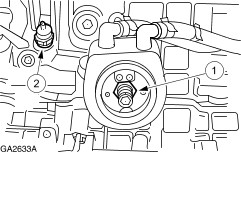
Remove the water pump. - Disconnect the coolant hose.
- Disconnect the oil cooler hose.
- Remove the bolts.
- Remove the pump.
| | | -
Remove the flywheel. - Remove the bolts.
- Remove the backing plate.
| | | -
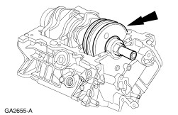
Install the special tool. | | | -
Remove the crankshaft oil seal. | | | -
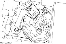
Remove the generator. - Remove the bracket bolt.
- Remove the generator bolts and remove the generator.
| | | -
Remove the bolts and the generator bracket. | | | -
NOTE:Remove the bolts in the indicated sequence. Remove the LH exhaust manifold. | | | -
Remove the oil pressure switch and the oil cooler. - Remove the oil cooler.
- Remove the oil pressure switch.
| | | -
Remove the studs and the oil pan heat shields. | | | -
NOTE:Remove the bolts and studs in the indicated sequence. Remove the oil pan. - Clean and inspect oil pan and cylinder block.
| | | -
Remove the inline connector bracket. - Remove the nuts.
- Remove the bracket.
| | | -
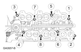
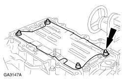
NOTE:Remove the bolts and studs in the indicated sequence. Remove the cylinder head covers. | | | -
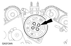
Using special tools, remove the water pump drive pulley. - Install special tool.
- Install special tool.
- Remove the water pump pulley.
| | | -
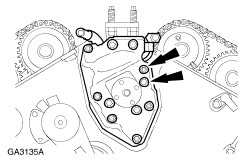
NOTE:In order to make sure correct sealing do not scratch the camshaft. Using the special tools, remove the camshaft oil seal. | | | -
CAUTION:Protect the camshaft surface when removing the oil seal retainer. Remove the bolts and the camshaft oil seal retainer. | | | -
Remove the bolts and the power steering pump pulley. | | | -
Remove the power steering pump and bracket. | | | -
NOTE:The crankshaft pulley bolt is tightened to yield and must not be reused. Remove the crankshaft pulley bolt. - Install the special tool to hold the crankshaft pulley.
- Remove crankshaft pulley bolt.
| | | -
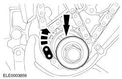
Using the special tool, remove the crankshaft pulley. | | | -
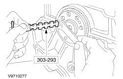
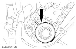
CAUTION:Protect the crankshaft surface when removing the front oil seal. Using the special tool, remove the crankshaft front oil seal. | | | -
Remove the position sensors. - Remove the bolt and the crankshaft position (CKP) sensor.
- Remove the bolt and the camshaft position (CMP) sensor.
| | | -
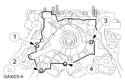
NOTE:Remove the bolts and studs in the indicated sequence. Remove the engine front cover. | | | -
NOTE:The pulse ring has two keyways, one for the 3.0L and one for the 2.5L. Remove the CKP sensor pulse wheel. | | | -
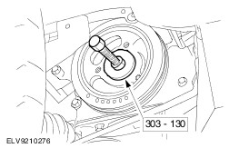
Install the crankshaft pulley and bolt. | | | -
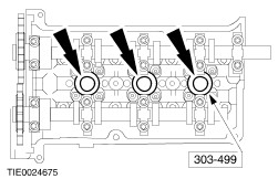
Remove the RH spark plugs. | | | -
Remove the LH spark plugs. | | | -
CAUTION:Rotate the crankshaft clockwise to position the crankshaft keyway to the 11 o'clock position and the engine to top dead center (TDC) No. 1 cylinder prior to the removal and installation of the camshafts and the roller followers or damage to the engine may occur. NOTE:Do not rotate the crankshaft counterclockwise. The timing chains may bind causing engine damage. Locate the crankshaft to the correct position. - Rotate the crankshaft keyway clockwise to the 11 o'clock position.
| | | -
Rotate the crankshaft clockwise to position the crankshaft keyway in the 3 o'clock position. - The RH camshafts are in the neutral position.
| | | -
NOTE:Mark the position of all chain drive components to be sure they are assembled in their original positions. Remove the RH chain tensioner and tensioner arm. - Remove the bolts, the chain tensioner and the tensioner adapter plate RH, if equipped.
- Remove the timing chain tensioner arm.
| | | -
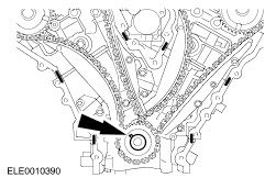
Remove the RH timing chain. - Remove the bolts and the fixed chain guide.
- Remove the RH timing chain.
| | | -
CAUTION:The cylinder head and the camshaft bearing caps are numbered to make sure they are reassembled in their original position. When removed, keep the bearing caps with the cylinder head they were removed from. Do not mix the caps. NOTE:Camshaft bearing caps are dowelled to cylinder head. As necessary, use a plastic mallet to loosen the caps. NOTE:Remove camshaft bearing thrust caps Nos. 1R and 5R first. Do not loosen any of the other bolts until the thrust caps are removed. NOTE:Loosen the bolts and bearing caps in the indicated sequence in several passes to allow the camshafts to gradually rise from the cylinder head. Loosen the camshafts (RH cylinder head). | | | -
NOTE:Verify that the LH camshaft sprocket RFF reference marks are aligned after rotating the crankshaft. Rotate the crankshaft clockwise two revolutions until the keyway is in the 11 o'clock position. | | | -
Remove the crankshaft pulley bolt and washer. | | | -
Remove the LH chain tensioner and tensioner arm. - Remove the chain tensioner bolts.
- Remove the chain tensioner and the tensioner adapter plate LH, if equipped.
- Remove the chain tensioner arm.
| | | -
Remove the LH timing chain. - Remove the bolts and the fixed chain guide.
- Remove the LH timing chain.
| | | -
CAUTION:The cylinder head and the camshaft bearing caps are numbered to make sure they are reassembled in their original position. When removed, keep the bearing caps with the cylinder head they were removed from. Do not mix the caps. NOTE:Remove camshaft bearing thrust caps Nos. 1L and 5L first. Do not loosen any of the other bolts until the thrust caps are removed. NOTE:Loosen the remaining bolts and bearing caps in the indicated sequence in several passes to allow the camshafts to gradually rise from the cylinder head. Loosen the camshafts (LH cylinder head). | | | -
NOTE:Remove the bolts in the indicated sequence. Remove the LH cylinder head. | | | -
NOTE:Remove the bolts in the indicated sequence. Remove the RH cylinder head. | | | -
Remove the power steering bracket. | | | -
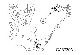
Remove the oil separator. | | | -
Remove the oil intake tube. - Remove the nut.
- Remove the bolts.
- Remove the oil intake tube.
| | | -
Remove the oil pan baffle. | | | -
NOTE:Remove the bolts in the indicated sequence. Remove the oil pump. | | | -
CAUTION:Pistons, connecting rods and connecting rod bearings should be numbered to make sure they are reassembled in the same position. NOTE:Mark the position of the connecting rod caps to the connecting rods to make sure correct installation. NOTE:Discard the connecting rod bolts after removal. Remove the connecting rod bolts, the connecting rod caps and the lower connecting rod bearings. | | | -
Inspect the tops of the cylinder bores. As necessary remove ridge and carbon build ups from each cylinder. | | | -
CAUTION:Using appropriate protection to prevent damage to the crankshaft bearing journals and cylinder bore surfaces. Install pieces of rubber hose to the connecting rods. | | | -
CAUTION:Care should be taken not to damage the connecting rod and cap joint face surfaces or possible engine damage may occur. Avoid contaminating the fracture joint surfaces with dirt or grease. NOTE:Reattach the connecting rods and caps after removal to avoid mismatch. Remove the pistons. - Rotate the crankshaft to locate pistons at the bottom of travel.
- Push the piston, connecting rod and upper bearing through the top of the cylinder.
| | | -
CAUTION:Bolt numbers 7 through 22 are tighten - to - yield and may not be reused. NOTE:Remove the bolts in the indicated sequence. Remove the lower cylinder block. | | | -
NOTE:Mark the position of the upper and lower crankshaft main bearing and the crankshaft thrust bearing for reassembly. Remove the lower crankshaft bearings. - Remove the lower crankshaft main bearings.
- Remove the lower crankshaft thrust main bearing.
| | | -
CAUTION:Avoid damage to any crankshaft bearing surfaces. NOTE:Never remove any pipe plugs or dowels unless they are to be newly installed or the cylinder block is to be washed. Remove the crankshaft. | | | -
Clean the cylinder block with a soap and water solution. Dry the cylinder block completely with compressed air. | | |