| Removal Special Tool(s) | | Separator, Ball Joint 211-020 (13-006) | | | Lifting Bracket, Engine 303-122 (21-068A) | General Equipment Floor crane Transmission jack Removal | | -
NOTE:The location of engine mountings and engine support insulators are described looking from the transaxle to the engine. | | | -
CAUTION:Disconnect the battery ground cable. | | | -
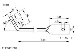
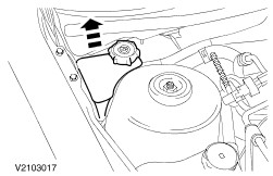
Make an auxiliary tool for fixing the hook in a wide-opened position. | | | -
Install the auxiliary tool to the hook. | | | -
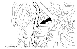
Remove the bolts and the water pump pulley cover. - Detach the coolant hose from the clip.
- Remove the bolts.
- Remove the cover.
| | | -
Remove the air cleaner (ACL). For additional information, refer to Section 303-12B . | | | -
Disconnect the accelerator and speed control cables. - Unclip the cables from the bracket.
- Disconnect the accelerator and speed control cables.
| | | -
Remove the selector cable. - Remove the bolts.
- Disconnect the cable.
| | | -
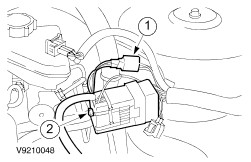
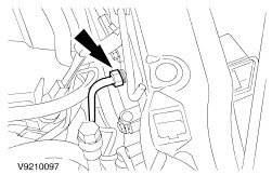
Disconnect the bulkhead electrical connector. - Disconnect the electrical connector.
- Remove the bolt and disconnect the electrical connector.
| | | -
Loosen the central junction box (CJB) and position it to one side. | | | -
Disconnect the cables. - Battery cables.
- Electrical connector.
- Ground cable.
| | | -
Disconnect the fan motor electrical connectors. | | | -
Remove the battery bracket bolts and remove the two ground cables. | | | -
Remove the battery bracket. | | | -
Disconnect the heater hoses. | | | -
Disconnect the coolant hoses from the radiator and from the coolant passage. | | | -
Disconnect the suction accumulator electrical connector. | | | -
Disconnect the evaporative emission (EVAP) hose. | | | -
Loosen both suspension strut nuts five turns. | | | -
Disconnect the upper intake vacuum supply line and the heater control vacuum hoses. | | | -
Drain the power steering fluid reservoir and pull it out (push-fit) and position it to one side. | | | -
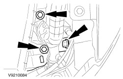
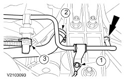
Disconnect the power steering hose. - Remove the bolt and the ground cable.
- Disconnect the power steering hose and position it to one side.
- Disconnect the connector.
| | | -
Disconnect the powertrain control module (PCM) and the ground cable. | | | -
Disconnect the coolant expansion tank hoses. | | | -
Remove the coolant expansion tank. - Disconnect the coolant level sensor connector.
- Remove the bolts.
| | | -
Remove the upper transaxle cooling tube. - Allow the fluid to drain into a suitable container.
- Close off the openings with plugs.
| | | -
Remove the fan (one screw on each side). | | | -
Disconnect the heated oxygen sensor (HO2S) electrical connector. | | | -
Remove the dual converter Y-pipe. | | | -
Remove the right-hand fender splash shields. | | | -
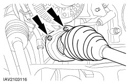
CAUTION:Do not damage boot or ABS sensor ring. NOTE:Right-hand side shown, left-hand side similar. Disconnect the suspension. - Disconnect the stabilizer link rods.
- Using the special tool, disconnect the tie-rod ends.
- Disconnect the lower suspension arm ball joints.
- Disconnect the ABS wiring harness brackets from the suspension struts.
| | | -
Remove the intermediate shaft bearing with the right-hand front drive halfshaft from the transaxle and secure using cable ties. | | | -
Remove the intermediate shaft bearing bracket. | | | -
Remove the left-hand front drive halfshaft from the transaxle and hang it up. | | | -
Disconnect and remove the HO2S electrical connector. | | | -
Remove the transaxle cooling line. | | | -
Remove the transaxle cooling line. | | | -
Remove the transaxle cooling line and the coolant hose from the radiator. | | | -
Disconnect the compressor electrical connector. | | | -
Remove the condenser core and tie it up. | | | -
Remove the fan shroud assembly. | | | -
Disconnect the HO2S electrical connector. | | | -
Check the accessory drive belt tension. - Fixed cast lug
- Moving stops
- Belt tensioner
- Adjustment is not possible.
| | | -
Check the accessory drive belt tension (continued). - Right-hand stop
- Drive belt
- Tensioning direction
- If the right-hand stop is touching the cast lug, install a new accessory drive belt during installation.
| | | -
Remove the accessory drive belt. | | | -
Remove the compressor heat shield. | | | -
Remove the compressor bracket bolts. - Secure the compressor with mechanics wire and position it to one side.
| | | -
NOTE:Use a Transmission jack to relieve pressure on the upport insulator. Remove the left-hand support insulator. - Remove the nuts.
- Remove the center bolt.
| | | -
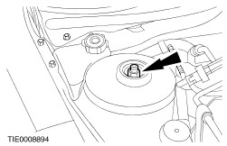
Remove the center bolt from the right-hand support insulator. | | | -
- Raise the engine slightly to prevent pressure from the support insulator.
| | | -
Remove the rear support insulator from the side member. | | | -
Remove the rear support insulator from the side member (continued). | | | -
Remove the engine with transaxle to the top. | | | -
Disconnect the following electrical connectors and position to one side. - Transmission range (TR) sensor.
- Transmission control connector.
- Engine coolant temperature (ECT) sensor connector
- Position the harness to one side.
| | | -
Disconnect the turbine shaft speed (TSS) sensor electrical connector. | | | -
Remove the oil level indicator tube. | | | -
Disconnect the starter motor and remove the starter motor bracket. | | | -
Disconnect the torque converter from the engine drive plate (four nuts). - Remove the plastic cover.
| | | -
Remove the right-hand flange bolts. | | | -
Remove the left-hand flange bolts. | | | -
Remove the lower flange bolts. | | | -
Remove the upper flange bolt. | | | -
WARNING:Do not let the torque converter drop out of the transaxle. Failure to follow this instruction may result in personal injury. Separate the automatic transaxle from the engine and install the special tool. | | |