| Disassembly and Assembly of Subassemblies Special Tool(s) | | Remover/Installer, King Pin Bushing 204-018 (14-011) | | | Remover/Installer, Lower Arm Bushing 204-058 (14-027) | | | Installer, Differential Bearing Cone 205-074 (15-035) | | | Remover/Installer, Pivot Bushing 205-297 (15-086) | | | Remover/Installer, Needle Bearing 307-286 (17-064) | | | Installer, Lube Tube 307-307 (17-065) | | | Installer, Extension Housing Bushing/Seal 308-045 (16-015) | Disassembly | | -
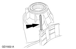
Remove and discard the final drive lubrication tube. | | | -
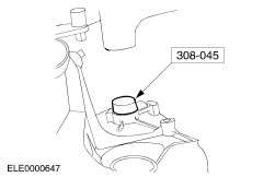
Using the special tool, remove and discard the final drive lubrication tube seal. | | | -
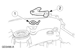
Remove the parking pawl ratcheting spring. | | | -
Remove the manual control lever assembly. | | | -
Remove the selector lever assembly. - Remove the nut.
- Remove the cam plate.
- Remove the drive plate.
- Remove the selector lever shaft.
| | | -
Remove selector lever shaft retaining bolt and bracket. | | | -
Remove the parking pawl shaft. | | | -
Remove the parking pawl assembly. - Remove the parking pawl.
- Remove the parking pawl return spring.
| | | -
CAUTION:Do not damage the transaxle case bore during seal removal. Remove and discard the manual control lever seal. | | | -
Remove the manual valve actuator rod (Z-link). | | | -
CAUTION:Do not damage the transaxle case sealing surface. NOTE:There are two retaining pins, one on either side of the manual valve detent lever. Remove and discard the manual valve detent lever assembly retaining pins. - Remove the detent lever retaining pin.
- Remove the detent lever shaft retaining pin.
| | | -
Remove the manual valve detent lever and shaft assembly. - Remove the manual valve detent lever and manual valve detent lever shaft from the transaxle case.
- Remove the manual valve detent lever from the transaxle case.
| | | -
CAUTION:Do not damage seal bore in the transaxle case during seal removal. Remove and discard the manual control seal. | | | -
Remove the line pressure port plug. | | | -
Remove and discard the cooler tube adaptor. | | | -
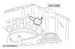
NOTE:The driven sprocket bearing No. 18 can only be replaced once. Should the bearing have been replaced previously a new transaxle case must be used. As necessary, remove the No. 18 driven sprocket bearing assembly from transaxle case. - Install the special tool at the inner side of the transaxle case.
- Install the special tool at the outer side of the transaxle case.
| | | -
WARNING:Eye protection should be worn when cleaning components with compressed air. Failure to follow these instructions may result in personal injury. Clean all components with a suitable solvent and use moisture-free compressed air to dry all parts and clean fluid passages. Check the following before assembling: - Final drive lubrication tube for damage.
- Manual control linkage for damage or wear.
- Case mating surfaces for nicks or deformation.
| Assembly | | -
CAUTION:Do not lubricate the outer surface of the No. 18 driven sprocket bearing assembly. NOTE:A new driven sprocket bearing No. 18 can be installed once before an installation of the transaxle case becomes necessary. If the No. 18 driven sprocket bearing has been installed previously and requires a second installation a new transaxle case must be installed. NOTE:The No. 18 driven sprocket bearing must be installed with the lettering on the needle bearing surface facing towards the Needle Bearing Replacer. Using the special tools, install the No.18 driven sprocket bearing assembly by pressing it into the transaxle case. - Position the special tool.
- Position the special tool.
- Install the No. 18 driven sprocket bearing.
| | | -
Install the fluid tube adaptor. - Install a new seal if necessary.
| | | -
Install the line pressure port plug. | | | -
Using the special tool, install a new manual valve seal. | | | -
Install the manual valve detent lever assembly, and the manual valve detent lever shaft assembly. - Install the manual valve detent lever into the transaxle case.
- Install the manual valve detent lever shaft into the transaxle case and lever.
| | | -
CAUTION:Do not allow the manual shaft retaining pin to contact the transaxle case. Install new retaining pins for the manual valve detent lever assembly. - Install the detent lever shaft retaining pin.
- Install the detent lever retaining pin.
- Verify the manual valve detent lever shaft rotates without binding.
| | | -
Install the manual valve actuator rod (Z-link). | | | -
Install the parking pawl assembly. - Install the parking pawl return spring.
- Install the parking pawl.
| | | -
Install the parking pawl shaft. | | | -
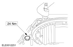
Install the parking pawl shaft retainer and bolt. | | | -
Using the special tool, install a new manual control lever seal. | | | -
NOTE:Lubricate the manual control lever inner shaft prior to installation. Install the manual control lever shaft assembly. - Install the selector lever shaft upwards.
- Install the drive plate.
- Install the cam plate.
- Install the nut.
| | | -
NOTE:Verify that the actuating cam rotates freely. Install the parking pawl ratcheting spring. | | | -
Install the manual control lever assembly and bolt. | | | -
Using the special tool, install a new final drive lubrication tube seal. | | | -
Install the final drive lubrication tube into the seal. | | | -
Using the special tool, install the final drive lubrication tube into the transaxle case. | |