ford Workshop Repair Guides

Ford Workshop Service and Repair Manuals

413-13 Parking Aid > < Warning Devices - Vehicles Built Up To: 05-1999
Warning Devices - Warning Devices—Vehicles Built From: 05/1999 Cougar 1999 (08/1998-01/2001)
Diagnosis and Testing

Refer to Wiring Diagrams Section 413-09, for schematic and connector information.

Inspection and Verification

  1. Verify the customer concern by operating the system.
  1. Visually inspect for obvious signs of mechanical or electrical damage.

Visual Inspection Chart

Mechanical Electrical
  • Door ajar switch
  • Safety belt minder buckle switch
  • Wiring harness
  • Loose or corroded connector(s)
  • Switch(es)
  1. If an obvious cause for an observed or reported concern is found, correct the cause (if possible) before proceeding to the next step.
  1. If the concern is not visually evident, verify the symptom and refer to the Symptom Chart.

Diagnostic Test Mode

The central timer module (CTM) is equipped with a self diagnostic feature. The feature will allow you to actuate three of the CTM outputs. Actuate the outputs one at a time in the following order:

  • Turn the wipers to position 1
  • Illuminate the heated rear window switch indicator
  • Illuminate the interior lamp

To prepare the vehicle for the Self-Diagnostic Mode, turn the windshield wiper switch to position 1, turn the interior lamp switch to the 12 SEC position and close both doors. To enter the Self-Diagnostic Mode press and hold the heated rear window switch while turning the ignition key to the ON position, release the heated rear window switch. The CTM will now enter the Self-Diagnostic Mode and wait for a command to activate the three outputs. Use the heated rear window switch to turn ON and then OFF each of the three CTM outputs.

To exit the Self-Diagnostic Mode, turn the ignition key OFF.

Symptom Chart

Symptom Chart

Symptom Possible Sources Action
All chimes are inoperative
*
Fuse(s)
*
Circuit(s).
*
CTM.
*
Central junction box (CJB).
*
GO to Pinpoint Test A. .
With headlamps ON, reminder chime does not operate correctly
*
Circuit(s).
*
Headlamp switch.
*
Door ajar switch.
*
CTM.
*
CJB.
*
GO to Pinpoint Test B. .
The safety belt minder feature does not operate correctly.
*
Circuit.
*
Safety belt minder buckle switch.
*
Instrument cluster.
*
CTM.
*
CJB.
*
REFER to Section  413-01 Instrument Cluster.

Pinpointtests

PINPOINT TEST A : ALL CHIMES ARE INOPERATIVE

TEST CONDITIONS DETAILS/RESULTS/ACTIONS
A1: CHECK CENTRAL TIMER MODULE (CTM) FOR VOLTAGE
1
Ignition switch in position 0.
2
Disconnect CTM C23.

3
Measure the voltage between the CTM pin 18, harness side and ground.

Is the voltage greater than 10 volts?
Yes
No
A2: CHECK CTM FOR VOLTAGE
1
Disconnect CJB C370.

2
Measure the voltage between the CJB C370 pin 2, circuit 30-DA4 (RD), harness side and ground.

Is the voltage greater than 10 volts?
Yes
INSTALL a new CJB. TEST the system for normal operation.
No
REPAIR the circuit. TEST the system for normal operation.
A3: CHECK CJB FOR OPEN

1
Measure the resistance between CTM C23, pin 16 component side and ground.

Is the resistance less than 5 ohms?
Yes
INSTALL a new CTM. TEST the system for normal operation.
No
A4: CHECK CIRCUIT 31-FA23 (BK) FOR OPEN
1
Connect C361 CJB.

2
Measure the resistance between the CJB C361 pin 10, circuit 31-FA23 (BK) harness side and ground.

Is the resistance less than 5 ohms?
Yes
INSTALL a new CJB. TEST the system for normal operation.
No
REPAIR the circuit. TEST the system for normal operation.

PINPOINT TEST B : WITH HEADLAMPS ON, REMINDER CHIME DOES NOT OPERATE CORRECTLY

TEST CONDITIONS DETAILS/RESULTS/ACTIONS
B1: CHECK THE INTERIOR LAMPS FOR CORRECT OPERATION
1
Check for operation of the illuminated entry from both the passenger and driver doors.

Is illuminated entry inoperative?
Yes
REFER to Section  417-02 Interior Lighting.
No
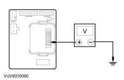
B2: CHECK THE CTM FOR VOLTAGE
1
Disconnect CTM C23.
2
Turn the headlamp switch to position 1.

3
Measure the voltage between the CTM pin 7, component side and ground.

Is the voltage greater than 10 volts?
Yes
No
B3: CHECK CIRCUIT 30S-DD40 (RD/GN) FOR VOLTAGE
1
Turn the headlamp switch to position 0.
2
Disconnect C361 CJB.
3
Turn the headlamp switch to position 1.

4
Measure the voltage between the CTM pin 4, circuit 30S-DD40 (RD/GN) harness side and ground.

Is the voltage greater than 10 volts?
Yes
INSTALL a new CJB. TEST the system for normal operation.
No
B4: CHECK HEADLAMP SWITCH FOR OPEN
1
Turn the headlamp switch to position 0.
2
Disconnect Headlamp Switch C320.
3
Turn the headlamp switch to position 1.
4
Measure the resistance between the headlamp switch C320 pin 14 and pin 5 component side.
5
Turn the headlamp switch to position 2.

6
Measure the resistance between the headlamp switch C320 pin 14 and pin 5 component side.

Is the resistance less than 5 ohms in position 1 and 2?
Yes
REPAIR circuit 29S-LE2 (RD). TEST the system for normal operation.
No
INSTALL a new headlamp switch. TEST the system for normal operation.
B5: CHECK CJB FOR OPEN

1
Measure the resistance between CTM C23, pin 16 component side and ground.

Is the resistance less than 5 ohms?
Yes
INSTALL a new CTM. TEST the system for normal operation.
No
B6: CHECK CIRCUIT 31-FA23 (BK) FOR OPEN
1
Connect C361 CJB.

2
Measure the resistance between the CJB C361 pin 10 circuit 31-FA23 (BK) harness side and ground.

Is the resistance less than 5 ohms?
Yes
INSTALL a new CJB. TEST the system for normal operation.
No
REPAIR the circuit. TEST the system for normal operation.

413-13 Parking Aid > < Warning Devices - Vehicles Built Up To: 05-1999