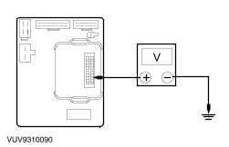
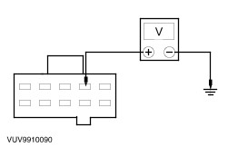
| Diagnosis and Testing Refer to Wiring Diagrams Section 417-01, for schematic and connector information.Refer to Wiring Diagrams Section 700-02, for schematic and connector information.Refer to Wiring Diagrams Section 413-01, for schematic and connector information. Special Tool(s) | | 73 Digital Multimeter or equivalent 105 - R0051 | Inspection and Verification - Verify the customer concern by operating the system.
- Visually inspect for obvious signs of mechanical and electrical damage.
Visual Inspection Chart | Mechanical | Electrical | | | - Wiring harness.
- Loose or corroded connector(s).
- Switch(es).
| - If an obvious cause for an observed or reported concern is found, correct the cause (if possible) before proceeding to the next step.
- If the concern is not visually evident, verify the symptom and refer to the Symptom Chart.
Diagnostic Test Mode The central timer module (CTM) is equipped with a self - diagnostic feature. This feature will allow you to actuate four of the CTM outputs. Actuate the outputs one at a time in the following order: - Turn the wipers on low speed
- Illuminate the heated rear window switch indicator
- Illuminate the interior lamp
- Illuminate the safety belt warning indicator in the instrument cluster
To prepare the vehicle for the self - diagnostic mode turn the windshield wiper switch to the low speed position, interior lamp to the 12 SEC position and close both doors. To enter the self diagnostic feature of the CTM hold the heated rear window switch while turning the ignition key to the on position, then release the heated rear window switch. The CTM is now in self - diagnostic mode and waiting for a command to activate the four outputs. Use the heated rear window switch to turn on and then off each of the four CTM outputs. To exit the self - diagnostic mode, turn the ignition key off. Symptom Chart Symptom Chart | Symptom | Possible Sources | Action | | All the chimes are inoperative | * Circuit. * Central timer module (CTM). * Central junction box (CJB). | * GO to Pinpoint Test A. | | With the headlamps ON, reminder chime does not operate correctly | * Headlamp switch. * Door ajar switch. * Central junction box. | * GO to Pinpoint Test B. | | The safety belt warning chime does not operate correctly | * Safety belt buckle switch. * Central junction box. * Circuit. * CTM. | * GO to Pinpoint Test C. | Pinpoint Tests | PINPOINT TEST A : ALL THE CHIMES/BUZZERS ARE INOPERATIVE | | TEST CONDITIONS | DETAILS/RESULTS/ACTIONS | | A1: CHECK CENTRAL TIMER MODULE (CTM) FOR VOLTAGE | | | 1 Ignition switch in position 0. | | | 2 Disconnect CTM C23. | | | 3 Measure the voltage between the CTM C23 pin 18 and ground. | | | Is the voltage greater than 10 volts? Yes No INSTALL a new central junction box. TEST the system for normal operation. | | A2: CHECK CENTRAL JUNCTION BOX FOR OPEN | | | 1 Disconnect CTM C23. | | | 2 Measure the resistance between CTM C23 pin 16 and ground. | | | Is the resistance less than 5 ohms? Yes INSTALL a new CTM. TEST the system for normal operation. No INSTALL a new central junction box. TEST the system for normal operation. | | PINPOINT TEST B : THE HEADLAMP REMINDER CHIME DOES NOT OPERATE CORRECTLY | | TEST CONDITIONS | DETAILS/RESULTS/ACTIONS | | B1: CHECK VOLTAGE INPUT FROM HEADLAMP SWITCH | | | 1 Disconnect CTM C23. | | | 2 Turn the headlamp switch to PARK. | | | 3 Turn the headlamp switch to LOW BEAM. | | | 4 Measure the voltage between the CTM C23 pin 7 and ground. | | | Is the voltage greater than 10 volts in both switch positions? Yes INSTALL a new CTM. TEST the system for normal operation. No If the voltage is greater than 10 volts only in one switch position, INSTALL a new headlamp switch. TEST the system for normal operation. | | B2: CHECK CIRCUIT 30S - DD40 (RD/GN) FOR VOLTAGE | | | 1 Measure the voltage between the CJB C361 pin 4, circuit 30S - DD40 (RD/GN), harness side and ground. | | | Is the voltage greater than 10 volts? Yes INSTALL a new CJB. TEST the system for normal operation. No | | B3: CHECK HEADLAMP SWITCH FOR OPEN | | | 1 Turn the headlamp switch to OFF. | | | 2 Disconnect Headlamp Switch C320. | | | 3 Turn the headlamp switch to PARK. | | | 4 Measure the resistance between the headlamp switch C320 pin 4 and pin 5. | | | 5 Turn the headlamp switch to LOW BEAM. | | | 6 Measure the resistance between the headlamp switch C320 pin 4 and pin 5. | | | Is the resistance less than 5 ohms in PARK and LOW BEAM? Yes REPAIR circuit 30S - DD40 (RD/GN). TEST the system for normal operation. No INSTALL a new headlamp switch. TEST the system for normal operation. | | PINPOINT TEST C : THE SAFETY BELT WARNING CHIME DOES NOT OPERATE CORRECTLY | | TEST CONDITIONS | DETAILS/RESULTS/ACTIONS | | C1: CHECK THE SAFETY BELT SWITCH FOR OPEN | | | 1 Ignition switch in position 0. | | | 2 Disconnect Safety Belt Switch C109. | | | 3 Measure the resistance between the safety belt switch C109 pin 1 and pine 2. | | | Is the resistance less than 5 ohms unbuckled and greater than 10,000 ohms buckled? Yes No INSTALL a new safety belt switch. TEST the system for normal operation. | | C2: CHECK CIRCUIT 31 - WC9 FOR OPEN | | | 1 Measure the resistance between the safety belt switch C109 pin 1 circuit 31 - WC9 (BK), harness side and ground. | | | Is the resistance less than 5 ohms? Yes No REPAIR the circuit. TEST the system for normal operation. | | C3: CHECK CIRCUIT 31S - WC9 (BK/RD) FOR OPEN | | | 1 Disconnect CJB C366. | | | 2 Measure the resistance between the safety belt switch C109 pin 2, circuit 31S CW9 (BK/RD), harness side and CJB C366 pin 1, circuit 31S - WC9 (BK/RD), harness side. | | | Is the resistance less than 5 ohms? Yes No REPAIR the circuit. TEST the system for normal operation. | | C4: CHECK CENTRAL JUNCTION BOX CIRCUIT | | | 1 Measure the resistance between the CTM C23 pin 15, and CJB C366 pin 1. | | | Is the resistance less than 5 ohms? Yes INSTALL a new CTM. TEST the system for correct operation. No INSTALL a new CJB. TEST the system for normal operation. | |