ford Workshop Repair Guides

Ford Workshop Service and Repair Manuals

Fog Lamps > < Turn Signal and Hazard Lamps
Exterior Lighting - Parking, Rear and License Plate Lamps Cougar 1999 (08/1998-01/2001)
Diagnosis and Testing

Refer to Wiring Diagrams Section 417-01, for schematic and connector information.

Inspection and Verification

  1. Switch on the parking lamp to verify the customer concern.
  1. Visually inspect for obvious signs of mechanical or electrical damage.

Visual Inspection Chart

Electrical
  • Wiring harness
  • Fuse(s)
  • Bulb(s)
  • Electrical connector(s)
  1. If an obvious cause for an observed or reported concern is found, correct the cause (if possible) before proceeding the next step.
  1. If the cause is not visually evident, verify the symptom and refer to the Symptom Chart

Symptom Chart

Symptom Possible Sources Action
The parking, rear or licence plate lamps are inoperative
*
Open circuit(s) (e.g. wiring, fuses, lamp switch or bulb outage module).
*
GO to Pinpoint Test J.
One or more parking, rear or licence plate lamps are inoperative
*
Open circuit(s) (e.g. wiring, fuses, lamp switch or bulb outage module).
*
GO to Pinpoint Test K.
Parking, rear or licence plate lamps are on continuously
*
Short circuit(s) to power (e.g. wiring, lamp switch or bulb outage module).
*
Go to Pinpoint Test L.

Pinpointtests

PINPOINT TEST A : THE PARKING, REAR OR LICENCE LAMPS ARE INOPERATIVE

TEST CONDITIONS DETAILS/RESULTS/ACTIONS
A1: DETERMINE THE FAULT CONDITION
1
Turn the lamp switch to the "Parking light" position.
2
Determine the fault condition. Vehicles with day time running lamps: REFER to Section  417-04 Daytime Running Lamps (DRL).

Are all parking, rear and licence plate lamps inoperative?
Yes
No
If the left-hand parking lamps are inoperative only with the lamp switch to the ”left-hand parking light" position: GO to A4.
If the right-hand parking lamps are inoperative only with the lamp switch in the ”right-hand parking light" position: GO to A8.
If the left-hand parking lamps are inoperative only with the lamp switch in the ”Parking light" position: GO to A11.
If the right-hand parking lamps are inoperative only with the lamp switch in the ”Parking light" position: GO to A15.
If the licence plate lamps are inoperative: GO to A18.
A2: DETERMINE THE FAULT CONDITION
1
Turn the lamp switch to the "Dipped beam" position and determine the fault condition.

Are the parking, rear or licence plate lamps inoperative?
Yes
No
INSTALL a new lamp switch. TEST the system for normal operation.
A3: CHECK THE VOLTAGE AT THE LAMP SWITCH
1
Ignition switch in position 0.
2
Disconnect Lamp switch C320.
3
Ignition switch in position II.

4
Measure the voltage between lamp switch, C320, pin 15, circuit 30-DA1 (RD), harness side and ground.

Is battery voltage indicated?
Yes
INSTALL a new lamp switch. TEST the system for normal operation.
No
REPAIR circuit 30-DA1 (RD) between lamp switch and splice S232 by using the wiring diagrams. TEST the system for normal operation.
A4: DETERMINE THE FAULT CONDITION
1
Turn the lamp switch to the "right-hand parking lamps" position and determine the fault condition.

Are the right-hand parking lamps inoperative?
Yes
No
A5: CHECK VOLTAGE AT THE LAMP SWITCH
1
Ignition switch in position 0.
2
Disconnect Lamp switch C320.
3
Ignition switch in position II.

4
Measure the voltage between lamp switch, connector C320, pin 5, circuit 30S-DA7 (RD/YE), harness side and ground.

Is battery voltage indicated?
Yes
INSTALL a new lamp switch. TEST the system for normal operation.
No
REPAIR circuit 30S-DA7 (RD/YE) between lamp switch, connector C320 and ignition switch, connector C456, pin 2 by using the wiring diagrams. TEST the system for normal operation.
A6: CHECK VOLTAGE AT FUSE F33 (CJB)
1
Turn the lamp switch to the ”left-hand parking lamps" position.

2
Measure the voltage between Fuse F33 (7.5 A) and ground.

Is battery voltage indicated?
Yes
Without bulb outage module: If fuse is OK, INSTALL a new CJB. TEST the system for normal operation.
With bulb outage module: If fuse is OK: GO to A16.
No
A7: CHECK CIRCUIT 30S-DA38 (RD/BU) AND 30S-DD38 (RD/BU) FOR OPEN
1
Ignition switch in position 0.
2
Disconnect Lamp switch C320.
3
Disconnect CJB C361.

4
Measure the resistance between lamp switch, connector C320, pin 13, circuit 30S-DA38 (RD/BU), harness side and CJB C361, pin 9 circuit 30S-DD38 (RD/BU), harness side.

Is the resistance less than 2 ohms?
Yes
INSTALL a new CJB. TEST the system for normal operation.
No
REPAIR circuit 30S-DA38 (RD/BU) or 30S-DD38 (RD/BU) by using the wiring diagrams. TEST the system for normal operation.
A8: DETERMINE THE FAULT CONDITION
1
Turn the lamp switch to the ”left-hand parking lamps" position and determine the fault condition.

Are the left-hand parking lamps inoperative?
Yes
No
A9: CHECK VOLTAGE AT FUSE F35 (CJB)
1
Turn the lamp switch to the ”right-hand parking lamps" position.

2
Measure the voltage between Fuse F35 (7.5 A) and ground.

Is battery voltage indicated?
Yes
Without bulb outage module: If fuse is OK, INSTALL a new CJB. TEST the system for normal operation.
With bulb outage module: If fuse is OK, GO to A17.
No
A10: CHECK CIRCUIT 30S-DA37 (RD/YE) OR 30S-DD37 (RD/YE) FOR OPEN
1
Ignition switch in position 0.
2
Disconnect Lamp switch C320.
3
Disconnect CJB C361.

4
Measure the resistance between lamp switch, connector C320, pin 2, circuit 30S-DA37 (RD/YE), harness side and CJB, connector C361, pin 7 circuit 30S-DD37 (RD/YE), harness side.

Is the resistance less than 2 ohms?
Yes
INSTALL a new CJB. TEST the system for normal operation.
No
REPAIR circuit 30S-DA37 (RD/YE) or 30S-DD37 (RD/YE) by using the wiring diagrams. TEST the system for normal operation.
A11: DETERMINE THE FAULT CONDITION
1
Turn the lamp switch to the "parking lamps" position.

Is the right-hand parking lamp inoperative?
Yes
No
A12: CHECK THE VOLTAGE AT THE LAMP SWITCH
1
Ignition switch in position 0.
2
Disconnect Lamp switch C320.
3
Ignition switch in position II.

4
Measure the voltage between lamp switch, connector C320, pin 15, circuit 30-DA1 (RD), harness side and ground.

Is battery voltage indicated?
Yes
INSTALL a new lamp switch. TEST the system for normal operation.
No
A13: CHECK VOLTAGE AT F40 (BJB)

1
Measure the voltage between F40 (20 A) (BJB), harness side and ground.

Is battery voltage indicated?
Yes
If fuse is OK: GO to A14.
No
If fuse is OK: INSTALL a new BJB. TEST the system for normal operation.
A14: CHECK CIRCUIT 30-LE21 (RD), 30-LE21A (RD), 30-LE21B (RD) OR 30-DA1 (RD) FOR OPEN
1
Ignition switch in position 0.

2
Measure the resistance between lamp switch, connector C320, pin 15, circuit 30-DA1 (RD) and F40 (BJB), harness side.

Is the resistance less than 2 ohms?
Yes
If fuse is OK, INSTALL a new BJB. TEST the system for normal operation.
No
REPAIR circuit 30-LE21 (RD), 30-LE21A (RD), 30-LE21B (RD) or 30-DA1 (RD) by using the wiring diagrams. TEST the system for normal operation.
A15: DETERMINE THE FAULT CONDITION
1
Turn the lamp switch to the ”Parking lamps" position.

Is the left-hand parking lamp inoperative?
Yes
No
A16: CHECK VOLTAGE AT BULB OUTAGE MODULE
1
Ignition switch in position 0.
2
Disconnect Bulb outage module C466.
3
Ignition switch in position II.
4
Turn the lamp switch to the ”Parking light" position.

5
Measure the voltage between bulb outage module, connector C466, pin 15, circuit 29S-GE31 (OG/WH), harness side and ground.

Is battery voltage indicated?
Yes
INSTALL a new bulb outage module. TEST the system for normal operation.
No
REPAIR circuit 29S-GE31 (OG/WH) by using the wiring diagrams. TEST the system for normal operation.
A17: CHECK VOLTAGE AT BULB OUTAGE MODULE
1
Ignition switch in position 0.
2
Disconnect Bulb outage module C466.
3
Ignition switch in position II.
4
Turn the lamp switch to the ”Parking light" position.

5
Measure the voltage between bulb outage module, connector C466, pin 20, circuit 29S-GE33 (OG/BU), harness side and ground.

Is battery voltage indicated?
Yes
INSTALL a new bulb outage module. TEST the system for normal operation.
No
REPAIR circuit 29S-GE33 (OG/BU) by using the wiring diagrams. TEST the system for normal operation.
A18: CHECK THE VOLTAGE AT FUSE F31 (7.5 A) (CJB)
1
Turn the lamp switch to the ”Parking lamps" position.

2
Measure the voltage between fuse F31 (7.5 A) (CJB), harness side and ground.

Is battery voltage indicated?
Yes
If fuse is OK, GO to A19.
No
If fuse is OK, GO to A21.
A19: CHECK THE VOLTAGE AT CONNECTOR C1914
1
Ignition switch in position 0.
2
Disconnect Connector C1914.
3
Ignition switch in position II.
4
Turn the lamp switch to the ”Parking light" position.

5
Measure the voltage between connector C1914, pin 1, circuit 29S-LF21 (OG/BK), harness side and ground.

Is battery voltage indicated?
Yes
REPAIR circuit 31-LF21 (BK) by using the wiring diagrams. TEST the system for normal operation.
No
A20: CHECK CIRCUIT 29S-LF21 (OG/BK) FOR OPEN
1
Ignition switch in position 0.
2
Disconnect CJB C367.

3
Measure the resistance between CJB, connector C367, circuit 29S-LF21 (OG/BK), harness side and connector C1914, pin 1, circuit 29S-LF21 (OG/BK), harness side.

Is the resistance less than 2 ohms?
Yes
INSTALL a new CJB. TEST the system for normal operation.
No
REPAIR circuit 29S-LF21 (OG/BK) by using the wiriring diagarms. TEST the system for normal operation.
A21: CHECK CIRCUIT 30S-DD40 (RD/GN) FOR VOLTAGE
1
Ignition switch in position 0.
2
Disconnect Connector C361.
3
Ignition switch in position II.
4
Turn the lamp switch to the ”Parking light" position.

5
Measure the voltage between CJB, connector C361, pin 4 circuit 30S-DD40 (RD/GN), harness side and ground.

Is battery voltage indicated?
Yes
INSTALL a new CJB. TEST the system for normal operation.
No
A22: CHECK CIRCUIT 30S-DA40 (RD/GN) AND 30S-DD40 (RD/GN) FOR OPEN
1
Ignition switch in position 0.
2
Disconnect Lamp switch C320.
3
Disconnect CJB C361.

4
Measure the resistance between lamp switch, connector C320, pin 14, circuit 30S-DA40 (RD/GN), harness side and CJB, connector C361, pin 4 circuit 30S-DD40 (RD/GN), harness side.

Is the resistance less than 2 ohms?
Yes
INSTALL a new lamp switch. TEST the system for normal operation.
No
REPAIR circuit 30S-DD40 (RD/GN) or 30S-DA40 (RD/GN) by using the wiring diagrams. TEST the system for normal operation.

PINPOINT TEST B : ONE OR MORE PARKING, REAR OR LICENCE PLATE LAMPS ARE INOPERATIVE

TEST CONDITIONS DETAILS/RESULTS/ACTIONS
B1: DETERMINE THE FAULT CONDITION
1
Turn the parking lamp switch to the "On" position and determine the fault condition. Vehicles with daytime running lamps: REFER to Section  417-04 Daytime Running Lamps (DRL).

Is the left-hand parking lamp inoperative?
Yes
No
If the left-hand rear lamp is inoperative: GO to B5.
If the right-hand parking lamp is inoperative: GO to B8.
If the right-hand rear lamps are inoperative: GO to B11.
If the left-hand licence plate lamp is inoperative: GO to B14.
If the right-hand licence plate lamp is inoperative: GO to B16.
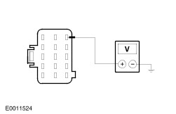
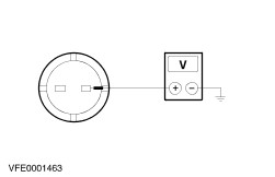
B2: CHECK THE POWER SUPPLY TO THE LEFT-HAND HEADLAMP
1
Turn the lamp switch to the "Off" position.
2
Ignition switch in position 0.
3
Disconnect Left-hand headlamp C835.
4
Ignition switch in position II.
5
Turn the lamp switch to the ”Parking light" position.

6
Measure the voltage between left-hand headlamp, connector C835, pin 4, circuit 29S-LF7 (OG/BU), harness side and ground.

Is battery voltage indicated?
Yes
No
Without bulb outage module: REPAIR circuit 29S-LF7 (OG/BU) by using the wiring diagrams. TEST the system for normal operation.
With bulb outage module: GO to B4.
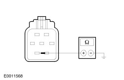
B3: CHECK CIRCUIT 31-LE15 (BK) FOR OPEN
1
Ignition switch in position 0.
2
Turn the lamp switch to the "Off" position.

3
Measure the resistance between left-hand headlamp, connector C835, pin 6, circuit 31-LE15 (BK), harness side and ground.

Is the resistance less than 2 ohms?
Yes
If the bulb is OK, INSTALL a new left-hand head lamp. TEST the system for normal operation.
No
REPAIR circuit 31-LE15 (BK) by using the wiring diagrams. TEST the system for normal operation.
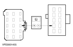
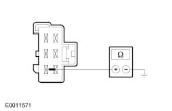
B4: CHECK CIRCUIT 29S-LF7 (OG/BU) FOR OPEN
1
Turn the lamp switch to the "Off" position.
2
Ignition switch in position 0.
3
Disconnect Left-hand headlamp C835.
4
Disconnect Bulb outage module C466.

5
Measure the resistance between left-hand headlamp, connector C835, pin 4, circuit 29S-LF7 (OG/BU), harness side and bulb outage module, connector C466, pin 17, circuit 29S-LF7 (OG/BU), harness side.

Is the resistance less than 2 ohms?
Yes
INSTALL a new bulb outage module. TEST the system for normal operation.
No
REPAIR circuit 29S-LF7 (OG/BU) by using the wiring diagrams. TEST the system for normal operation.
B5: CHECK THE LEFT-HAND REAR LAMP FOR VOLTAGE
1
Turn the lamp switch to the "Off" position.
2
Ignition switch in position 0.
3
Disconnect Left-hand rear lamp C446.
4
Ignition switch in position II.
5
Turn the lamp switch to the ”Parking light" position.

6
Measure the voltage between left-hand rear lamp, connector C446, pin 4, circuit 29S-LF11 (OG/WH), harness side and ground.

Is battery voltage indicated?
Yes
No
Without bulb outage module: REPAIR circuit 29S-LF11 (OG/WH) by using the wiring diagrams. TEST the system for normal operation.
With bulb outage module: GO to B7.
B6: CHECK CIRCUIT 31-LF11 (BK) FOR OPEN
1
Turn the lamp switch to the "Off" position.

2
Measure the resistance between left-hand rear lamp, connector C446, pin 6, circuit 31-LF11 (BK), harness side and ground.

Is the resistance less than 2 ohms?
Yes
If the bulb is OK, INSTALL a new left-hand rear lamp assembly. TEST the system for normal operation.
No
REPAIR circuit 31-LF11 (BK) by using the wiring diagrams. TEST the system for normal operation.
B7: CHECK CIRCUIT 29S-LF11 (OG/WH) FOR OPEN
1
Turn the lamp switch to the "Off" position.
2
Ignition switch in position 0.
3
Disconnect Bulb outage module C466.

4
Measure the resistance between bulb outage module, connector C466, pin 18, circuit 29S-LF11 (OG/WH), harness side and left-hand rear lamp, connector C446, pin 4, circuit 29S-LF11 (OG/WH), harness side.

Is the resistance less than 2 ohms?
Yes
INSTALL a new bulb outage module. TEST the system for normal operation.
No
REPAIR circuit 29S-LF11 (OG/WH) by using the wiring diagrams. TEST the system for normal operation.
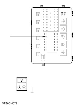
B8: CHECK CIRCUIT 29S-LF16 (OG/GN) FOR OPEN
1
Turn the lamp switch to the "Off" position.
2
Ignition switch in position 0.
3
Disconnect Right-hand headlamp C834.
4
Ignition switch in position II.
5
Turn the lamp switch to the ”Parking light" position.

6
Measure the voltage between right-hand headlamp, connector C834, pin 4, circuit 29S-LF16 (OG/GN), harness side and ground.

Is battery voltage indicated?
Yes
No
Without bulb outage module: REPAIR circuit 29S-LF16 (OG/GN) by using the wiring diagrams. TEST the system for normal operation.
With bulb outage module: GO to B10.
B9: CHECK CIRCUIT 31-LE22 (BK) FOR OPEN
1
Ignition switch in position 0.

2
Measure the resistance between right-hand headlamp, connector C834, pin 6, circuit 31-LE22 (BK), harness side and ground.

Is the resistance less than 2 ohms?
Yes
If the bulb is OK, INSTALL a new right-hand headlamp assembly. TEST the system for normal operation.
No
REPAIR circuit 31-LE22 (BK) by using the wiring diagrams. TEST the system for normal operation.
B10: CHECK CIRCUIT 29S-LF16 (OG/GN)
1
Ignition switch in position 0.
2
Disconnect Bulb outage module C466.

3
Measure the resistance between bulb outage module, connector C466, pin 21, circuit 29S-LF16 (OG/GN), harness side and right-hand headlamp, connector C834, pin 4, circuit 29S-LF16 (OG/GN), harness side.

Is the resistance less than 2 ohms?
Yes
INSTALL a new bulb outage module. TEST the system for normal operation.
No
REPAIR circuit 29S-LF16 (OG/GN) by using the wiring diagrams. TEST the system for normal operation.
B11: CHECK THE RIGHT-HAND REAR LAMP FOR VOLTAGE
1
Turn the lamp switch to the "Off" position.
2
Ignition switch in position 0.
3
Disconnect Rear lamp right-hand side C447.
4
Ignition switch in position II.
5
Turn the lamp switch to the ”Parking light" position.

6
Measure the voltage between left-hand rear lamp, connector C447, pin 4, circuit 29S-LF20 (OG), harness side and ground.

Is battery voltage indicated?
Yes
No
Without bulb outage module: REPAIR circuit 29S-LF20 (OG) by using the wiring diagrams. TEST the system for normal operation.
With bulb outage module: GO to B13.
B12: CHECK CIRCUIT 31-LF20 (BK) FOR OPEN
1
Ignition switch in position 0.
2
Turn the lamp switch to the "Off" position.

3
Measure the resistance between left-hand rear lamp, connector C447, pin 6, circuit 31-LF20 (BK), harness side and ground.

Is the resistance less than 2 ohms?
Yes
If the bulb is OK, INSTALL a new rear lamp assembly. TEST the system for normal operation.
No
REPAIR the circuit 31-LF20 (BK) by using the wiring diagrams. TEST the system for normal operation.
B13: CHECK CIRCUIT 29S-LF20 (OG) FOR OPEN
1
Turn the lamp switch to the "Off" position.
2
Ignition switch in position 0.
3
Disconnect Bulb outage module C466.

4
Measure the resistance between bulb outage module, connector C466, pin 13, circuit 29S-LF20 (OG), harness side and right-hand rear lamp, connector C447, pin 4, circuit 29S-LF20 (OG), harness side.

Is the resistance less than 2 ohms?
Yes
INSTALL a new bulb outage module. TEST the system for normal operation.
No
REPAIR circuit 29S-LF20 (OG) by using the wiring diagrams. TEST the system for normal operation.
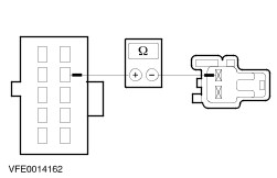
B14: CHECK THE LEFT-HAND LICENCE PLATE LAMP FOR VOLTAGE
1
Turn the lamp switch to the "Off" position.
2
Ignition switch in position 0.
3
Disconnect Licence plate lamp left-hand side C491.
4
Ignition switch in position II.
5
Turn the lamp switch to the ”Parking light" position.

6
Measure the voltage between licence plate lamp left-hand side, connector C491, circuit 29S-LF21 (OG/BK), harness side and ground.

Is battery voltage indicated?
Yes
No
REPAIR circuit 29S-LF21 (OG/BK) by using the wiring diagrams. TEST the system for normal operation.
B15: CHECK CIRCUIT 31-LF21 (BK) FOR OPEN

1
Measure the resistance between licence plate lamp left-hand side, connector C491, circuit 31-LF21 (BK), harness side and ground.

Is the resistance less than 2 ohms?
Yes
If the bulb is OK, INSTALL a new licence plate lamp left-hand side. TEST the system for normal operation.
No
REPAIR circuit 31-LF21 (BK) by using the wiring diagrams. TEST the system for normal operation.
B16: CHECK CIRCUIT 29S-LF22 (OG/BK) FOR OPEN
1
Turn the lamp switch to the "Off" position.
2
Ignition switch in position 0.
3
Disconnect Licence plate lamp right-hand side C492.
4
Ignition switch in position II.
5
Turn the lamp switch to the ”Parking light" position.

6
Measure the voltage between licence plate lamp right-hand side, connector C492, circuit 29S-LF22 (OG/BK), harness side and ground.

Is battery voltage indicated?
Yes
No
REPAIR circuit 29S-LF22 (OG/BK) by using the wiring diagrams. TEST the system for normal operation.
B17: CHECK CIRCUIT 31-LF21 (BK) FOR OPEN
1
Turn the lamp switch to the "Off" position.
2
Ignition switch in position 0.

3
Measure the resistance between right-hand licence plate lamp, connector C492, circuit 31-LF22 (BK), harness side and ground.

Is the resistance less than 2 ohms?
Yes
If the bulb is OK, INSTALL a new licence plate lamp right-hand side. TEST the system for normal operation.
No
REPAIR circuit 31-LF22 (BK) by using the wiring diagrams. TEST the system for normal operation.

PINPOINT TEST C : PARKING, REAR OR LICENCE PLATE LAMPS ARE ON CONTINUOUSLY

TEST CONDITIONS DETAILS/RESULTS/ACTIONS
C1: DETERMINE THE FAULT CONDITION
1
Determine the fault condition. Vehicles with day time running lamps: REFER to Section  417-04 Daytime Running Lamps (DRL).

Are the licence plate lamps on continuously?
Yes
No
The parking and rear lamps are on continuously: GO to C6.
C2: CHECK THE LAMP SWITCH
1
Ignition switch in position 0.
2
Disconnect Lamp switch C320.
3
Ignition switch in position II.
4
Determine the fault condition.

Are the licence plate lamps on continuously?
Yes
No
INSTALL a new lamp switch. TEST the system for normal operation.
C3: CHECK CIRCUIT 30S-DA40 (RD/GN) OR 30S-DD40 (RD/GN) FOR SHORT TO POWER
1
Ignition switch in position 0.
2
Disconnect CJB C361.
3
Ignition switch in position II.
4
Determine the fault condition.

Are the licence plate lamps on continuously?
Yes
No
REPAIR circuit 30S-DA40 (RD/GN) or 30S-DD40 (RD/GN) by using the wiring diagrams. TEST the system for normal operation.
C4: CHECK THE CENTRAL TIMER MODULE
1
Ignition switch in position 0.
2
Disconnect CTM C23.
3
Ignition switch in position II.
4
Determine the fault condition.

Are the licence plate lamps on continuously?
Yes
No
INSTALL a new CTM. TEST the system for normal operation.
C5: CHECK CJB
1
Ignition switch in position 0.
2
Connect CTM C23.
3
Disconnect CJB C367.
4
Ignition switch in position II.
5
Determine the fault condition.

Are the licence plate lamps on continuously?
Yes
REPAIR circuit 29S-LF21 (OG/BK) or 29S-LF22 (OG/BK) by using the wiring diagrams. TEST the system for normal operation.
No
INSTALL a new CJB. TEST the system for normal operation.
C6: CHECK THE LAMP SWITCH
1
Ignition switch in position 0.
2
Disconnect Lamp switch C320.
3
Ignition switch in position II.
4
Determine the fault condition.

Are the parking and rear lamps on continuously?
Yes
No
INSTALL a new lamp switch. TEST the system for normal operation.
C7: DETERMINE THE FAULT CONDITION
1
Determine the fault condition.

Are the left-hand lamps on continuously?
Yes
No
The right-hand lamps are on continuously: GO to C11.
C8: CHECK CIRCUIT 30S-DD38 (RD/BU) OR 30S-DA38 (RD/BU) FOR OPEN
1
Ignition switch in position 0.
2
Disconnect CJB C361.
3
Ignition switch in position II.
4
Determine the fault condition.

Are the left-hand lamps on continuously?
Yes
No
REPAIR the circuit 30S-DD38 (RD/BU) or 30S-DA38 (RD/BU) by using the wiring diagrams. TEST the system for normal operation.
C9: CHECK CJB
1
Ignition switch in position 0.
2
Disconnect CJB C369.
3
Ignition switch in position II.
4
Determine the fault condition.

Are the left-hand lamps on continuously?
Yes
With bulb outage module: GO to C10.
Without bulb outage module: Left-hand parking lamp is on continuously: REPAIR circuit 29S-LF7 (OG/BU) by using the wiring diagrams. TEST the system for normal operation.
Left-hand rear lamp is on continuously: REPAIR circuit 29S-LF11 (OG/WH) by using the wiring diagrams. TEST the system for normal operation.
No
INSTALL a new CJB. TEST the system for normal operation.
C10: CHECK CIRCUIT 29S-GE31 (OG/WH)
1
Ignition switch in position 0.
2
Disconnect Bulb outage module C466.
3
Ignition switch in position II.
4
Determine the fault condition.

Are the left-hand lamps on continuously?
Yes
Left-hand parking lamp is on continuously: REPAIR circuit 29S-LF7 (OG/BU) by using the wiring diagrams. TEST the system for normal operation.
Left-hand rear lamp is on continuously: REPAIR circuit 29S-LF11 (OG/WH) by using the wiring diagrams. TEST the system for normal operation.
No
REPAIR circuit 29S-GE31 (OG/WH) by using the wiring diagrams. If circuit is OK, INSTALL a new bulb outage module. TEST the system for normal operation.
C11: CHECK CIRCUIT 30S-DD37 (RD/YE) OR 30S-DA37 (RD/YE)
1
Ignition switch in position 0.
2
Disconnect CJB C361.
3
Ignition switch in position II.
4
Determine the fault condition.

Are the right-hand lamps on continuously?
Yes
No
REPAIR circuit 30S-DD37 (RD/YE) or 30S-DA37 (RD/YE) by using the wiring diagrams. If circuits are OK, INSTALL a new CJB. TEST the system for normal operation.
C12: CHECK CJB
1
Ignition switch in position 0.
2
Disconnect CJB C369.
3
Ignition switch in position II.
4
Determine the fault condition.

Are the right-hand lamps on continuously?
Yes
With bulb outage module. GO to C13.
Without bulb outage module: Left-hand parking lamp is on continuously: REPAIR circuit 29S-LF16 (OG/GN) by using the wiring diagrams. TEST the system for normal operation.
Left-hand rear lamp is on continuously: REPAIR circuit 29S-LF20 (OG) by using the wiring diagrams. TEST the system for normal operation.
No
INSTALL a new CJB. TEST the system for normal operation.
C13: CHECK CIRCUIT 29S-GE33 (OG/BU)
1
Ignition switch in position 0.
2
Disconnect Bulb outage module C466.
3
Ignition switch in position II.
4
Determine the fault condition.

Are the right-hand lamps on continuously?
Yes
Left-hand parking lamp is on continuously: REPAIR circuit 29S-LF16 (OG/GN) by using the wiring diagrams. TEST the system for normal operation.
Left-hand rear lamp is on continuously: REPAIR circuit 29S-LF20 (OG) by using the wiring diagrams. TEST the system for normal operation.
No
REPAIR circuit 29S-GE33 (OG/BU) by using the wiring diagrams. If circuit is OK, INSTALL a new bulb outage module. TEST the system for normal operation.

Fog Lamps > < Turn Signal and Hazard Lamps