| PINPOINT TEST A : THE DIRECTION INDICATOR LAMPS ARE INOPERATIVE/ON CONTINUOUSLY |
| TEST CONDITIONS | DETAILS/RESULTS/ACTIONS |
| A1: CHECK CIRCUIT 15-LG25 (GN/BU) FOR VOLTAGE |
| | 1 Ignition switch in position 0. |
| | 2 Disconnect Multifunction switch C459. |
| | 3 Ignition switch in position II. |
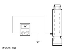
| | 4 Measure the voltage between multifunction switch, connector C459, pin 11, circuit 15-LG25 (GN/BU), harness side and ground. |
| | Is battery voltage indicated? Yes No REPAIR circuit 15-LG25 (GN/BU) by using the wiring diagrams. TEST the system for normal operation. |
| A2: CHECK MULTIFUNCTION SWITCH AND DIRECTION INDICATOR RELAY |
| | 1 Check the multifunction switch and direction indicator relay; refer to the multifunction switch and direction indicator relay component test. |
| | Are multifunction switch and direction indicator relay OK? Yes No INSTALL a new multifunction switch or direction indicator relay. TEST the system for normal operation. |
| A3: CHECK MULTIFUNCTION SWITCH FOR GROUND |
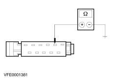
| | 1 Measure the resistance between multifunction switch, connector C459, pin 7, circuit 31-LG25 (BK), harness side and ground. |
| | Is the resistance less than 2 ohms? Yes No REPAIR circuit 31-LG25 (BK) by using the wiring diagrams. TEST the system for normal operation. |
| A4: DETERMINE THE INOPERATIVE LAMPS |
| | 1 Check which direction indicator lamps are inoperative. |
| | Are the left-hand direction indicator lamps inoperative? Yes No The right-hand direction indicator lamps are malfunctioning: GO to A13. |
| A5: DETERMINE THE FAULT |
| | 1 Check the malfunction of the left-hand direction indicator lamps. |
| | Are the left-hand direction indicator lamps on continuously? Yes No |
| A6: CHECK CIRCUIT 49S-LG1 (BU) FOR OPEN |
| | 1 Ignition switch in position 0. |
| | 2 Disconnect CJB C372. |
| | 3 Disconnect Multifunction switch C459. |
| | 4 Measure the resistance between multifunction switch, connector C459, pin 8, circuit 49S-LG1 (BU), harness side and CJB, connector C372, pin 9, circuit 49S-LG1 (BU), harness side. |
| | Is the resistance less than 2 ohms? Yes INSTALL a new CJB. TEST the system for normal operation. No REPAIR circuit 49S-LG1 (BU) by using the wiring diagrams. TEST the system for normal operation. |
| A7: CHECK CJB, DIRECTION INDICATOR AND HAZARD LAMPS FOR SHORT TO POWER |
| | 1 Ignition switch in position 0. |
| | 2 Disconnect CJB C362. |
| | 3 Disconnect CJB C367. |
| | 4 Disconnect CJB C369. |
| | 5 Disconnect CJB C372. |
| | 6 Ignition switch in position II. |
| | Are the left-hand direction indicator lamps inoperative? Yes No Left-hand direction indicator warning light on: CHECK circuit 49-LG15 (BU/BK) for short to power. If harness is OK INSTALL a new Instrument cluster. TEST the system for normal operation. Left-hand front direction indicator is on continuously: CHECK circuit 49-LG13 (BU/RD) or 49-LG11 (BU/OG) for short to power. TEST the system for normal operation. Left-hand rear direction indicator is on continuously: CHECK circuit 49-LG12 (BU) for short to power. TEST the system for normal operation. |
| A8: CHECK CJB FOR SHORT TO POWER |
| | 1 Ignition switch in position 0. |
| | 2 Connect CJB C367. |
| | 3 Ignition switch in position II. |
| | Is the left-hand rear direction indicator lamp on? Yes INSTALL a new CJB. TEST the system for normal operation. No |
| A9: CHECK CJB FOR SHORT TO POWER |
| | 1 Ignition switch in position 0. |
| | 2 Connect CJB C369. |
| | 3 Ignition switch in position II. |
| | Is the left-hand front direction indicator lamp on? Yes INSTALL a new CJB. TEST the system for normal operation. No |
| A10: CHECK CJB FOR SHORT TO POWERR |
| | 1 Ignition switch in position 0. |
| | 2 Connect CJB C362. |
| | 3 Ignition switch in position II. |
| | Is the direction indicator warning light on? Yes INSTALL a new CJB. TEST the system for normal operation. No CHECK circuit 49S-LG1 (BU) for short to power. TEST the system for normal operation. |
| A11: CHECK ANTI-THEFT FLASHER RELAY |
| | 1 Ignition switch in position 0. |
| | 2 Connect Anti-theft flasher relay left-hand side C2107. |
| | 3 Ignition switch in position II. |
| | Are the left-hand direction indicator lamps on? Yes CHECK circuit 49S-GL23 (BU/OG) for short to power. TEST the system for normal operation. No |
| A12: CHECK ANTI-THEFT MODULE |
| | 1 Ignition switch in position 0. |
| | 2 Connect Ant-theft flasher relay left-hand side C2107. |
| | 3 Disconnect Anti-theft module C451b. |
| | 4 Ignition switch in position II. |
| | Are the left-hand direction indicator lamps on continuously? Yes CHECK circuit 31S-GL24 (BK/YE) for short to ground. If circuit is OK, INSTALL a new anti-theft flasher relay. TEST the system for normal operation. No INSTALL a new anti-theft module. TEST the system for normal operation. |
| A13: DETERMINE THE FAULT |
| | 1 Check the malfunction of the right-hand direction indicator lamps. |
| | Are the right-hand direction indicator lamps on continuously? Yes No |
| A14: CHECK CIRCUIT 49S-LG2 (BU/RD) FOR OPEN |
| | 1 Ignition switch in position 0. |
| | 2 Disconnect Multifunction switch C459. |
| | 3 Disconnect CJB C372. |
| | 4 Measure the resistance between multifunction switch, connector C459, pin 9, circuit 49S-LG2 (BU/RD), harness side and CJB, connector C372, pin 8, circuit 49S-LG2 (BU/RD), harness side. |
| | Is the resistance less than 2 ohms? Yes INSTALL a new CJB. TEST the system for normal operation. No REPAIR circuit 49S-LG2 (BU/RD) by using the wiring diagrams. TEST the system for normal operation. |
| A15: CHECK CJB, DIRECTION INDICATOR AND HAZARD LAMPS FOR SHORT TO POWER |
| | 1 Ignition switch in position 0. |
| | 2 Disconnect CJB C362. |
| | 3 Disconnect CJB C367. |
| | 4 Disconnect CJB C369. |
| | 5 Disconnect CJB C372. |
| | 6 Ignition switch in position II. |
| | Are the right-hand direction indicator lamps inoperative? Yes No Right-hand direction indicator warning light is on continuously: CHECK circuit 49-LG22 (BU/YE) for short to power. If harness is OK, INSTALL a new instrument cluster. TEST the system for normal operation. Right-hand front direction indicator lamp is on continuously: CHECK circuit 49-LG20 (BU/WH) or 49-LG18 (BU) for short to power. Test the system for normal operation. Right-hand rear direction indicator lamp is on continuously: CHECK circuit 49-LG19 (BU/RD) for short to power. TEST the system for normal operation. |
| A16: CHECK CJB FOR SHORT TO POWER |
| | 1 Ignition switch in position 0. |
| | 2 Connect CJB C367. |
| | 3 Ignition switch in position II. |
| | Is the right-hand rear direction indicator lamp on continuously? Yes INSTALL a new CJB. TEST the system for normal operation. No |
| A17: CHECK CJB FOR SHORT TO POWER |
| | 1 Ignition switch in position 0. |
| | 2 Connect CJB C369. |
| | 3 Ignition switch in position II. |
| | Is the right-hand front direction indicator lamp on continuously? Yes INSTALL a new CJB. TEST the system for normal operation. No |
| A18: CHECK CJB FOR SHORT TO POWER |
| | 1 Ignition switch in position 0. |
| | 2 Connect CJB C362. |
| | 3 Ignition switch in position II. |
| | Is the right-hand direction indicator warning light on continuously? Yes INSTALL a new CJB. TEST the system for normal operation. No CHECK circuit 49S-LG2 (BU/RD) for short to power. TEST the system for normal operation. |
| A19: CHECK ANTI-THEFT FLASHER RELAY |
| | 1 Ignition switch in position 0. |
| | 2 Disconnect Anti-theft flasher relay left-hand side C2107. |
| | 3 Ignition switch in position II. |
| | Are the right-hand direction indicator lamps on continuously? Yes CHECK circuit 49S-GL25 (BU/WH) for short to power. TEST the system for normal operation. No |
| A20: CHECK ANTI-THEFT MODULE |
| | 1 Ignition switch in position 0. |
| | 2 Connect Anti-theft flasher relay left-hand side C2107. |
| | 3 Disconnect Anti-theft module C451b. |
| | 4 Ignition switch in position II. |
| | Are the right-hand direction indicator lamps on continuously? Yes CHECK circuit 31S-GL24 (BK/YE) for short to ground. If circuit is OK, INSTALL a new anti-theft flasher relay. TEST the system for normal operation. No INSTALL a new anti-theft module. TEST the system for normal operation. |