| Diagnosis and Testing Refer to Wiring Diagrams Section 417-01, for schematic and connector information. Inspection and Verification - Verifiy the customer concern.
- Visually inspect for obvious signs of mechanical or electrical damage.
Visual Inspection Chart | Electrical | - Fuse(s).
- Wiring harness.
- Electrical connector(s).
- Bulb(s).
| - If an obvious cause for an observed or reported concern is found, correct the cause (if possible) before proceeding to the next step.
- If the cause is not visually evident, verify the symptom and refer to the Symptom Chart.
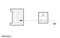
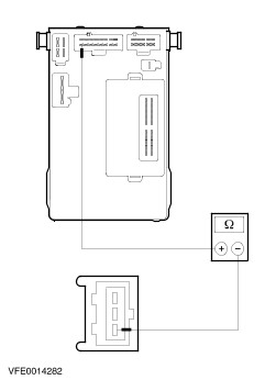
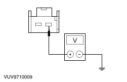
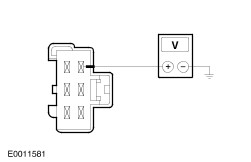
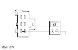
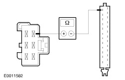
Symptom Chart | Symptom | Possible Sources | Action | | The stop lamps are inoperative | * Open circuit(s) (e.g. wiring, fuses, bulb outage module or brake pedal position (BPP) switch). | * | | One or more stop lamps are inoperative | * Open circuit(s) (e.g. wiring, fuses or bulb outage module). | * | | The stop lamps are on continuously | * Short circuit(s) to power (e.g. bulb outage module, PCM, BPPswitch, ABS module or speed control module). | * | Pinpointtests NOTE:Use a digital multimeter for all electrical measurements. | PINPOINT TEST A : THE STOP LAMPS ARE INOPERATIVE | | TEST CONDITIONS | DETAILS/RESULTS/ACTIONS | | A1: CHECK THE BRAKE PEDAL POSITION (BPP) SWITCH FOR VOLTAGE | | | 1 Ignition switch in position 0. | | | 2 Disconnect BPP switch C444. | | | 3 Ignition switch in position II. | | | 4 Measure the voltage between BPP switch, connector C444, pin 1, circuit 15-LG23 (GN/WH), harness side and ground. | | | Is battery voltage indicated? Yes No | | A2: CHECK F24 (CJB) FOR VOLTAGE | | | 1 Measure the voltage between fuse F24 (15 A) (CJB) and ground. | | | Is battery voltage indicated? Yes No If ignition relay is OK, INSTALL a new CJB. TEST the system for normal operation. | | A3: CHECK CIRCUIT 15-LG23 (GN/WH) FOR OPEN | | | 1 Ignition switch in position 0. | | | 2 Disconnect CJB C369. | | | 3 Measure the resistance between CJB, connector C369, pin 1, circuit 15-LG23 (GN/WH), harness side and BPP switch, connector C444, pin 1, circuit 15-LG23 (GN/WH), harness side. | | | Is the resistance less than 2 ohms? Yes INSTALL a new CJB. TEST the system for normal operation. No REPAIR circuit 15-LG23 (GN/WH) by using the wiring diagrams. TEST the system for normal operation. | | A4: CHECK THE BRAKE PEDAL POSITION (BPP) SWITCH | | | 1 Ignition switch in position II. | | | 2 Use a fused (15 A) jumper wire and connect at the brake pedal position switch, connector C444 between pin 1 and pin 3, harness side. | | | Are the stop lamps inoperative? Yes REPAIR circuit 15S-LG23 (GN/WH) between connector C444 and splice S367 by using the wiring diagrams. TEST the system for normal operation. Vehicle with bulb outage module: GO to A5. No INSTALL a new BPP switch. TEST the system for normal operation. | | A5: CHECK THE BULB OUTAGE MODULE FOR VOLTAGE | | | 1 Ignition switch in position 0. | | | 2 Disconnect Bulb outage module C466. | | | 3 Ignition switch in position II. | | | 4 Depress the brake pedal during the measurement. | | | 5 Measure the voltage between bulb outage module, connector C466, pin 16, circuit 15S-GE34 (GN/RD), harness side and ground. | | | Is battery voltage indicated? Yes INSTALL a new bulb outage module. TEST the system for normal operation. No REPAIR circuits between, connector C444, pin 3, circuit 15S-LG23 (GN/WH), splice S367 and connector C466, pin 16, circuit 15S-GE34 (GN/RD) by using the wiring diagrams. TEST the system for normal operation. | | PINPOINT TEST B : ONE OR MORE STOP LAMPS ARE INOPERATIVE - WITHOUT BULB OUTAGE MODULE | | TEST CONDITIONS | DETAILS/RESULTS/ACTIONS | | B1: DETERMINE THE INOPERATIVE LAMP | | | 1 Ignition switch in position II. | | | 2 Depress the brake pedal and determine the inoperative lamp. | | | Is the high-mounted stop lamp inoperative? Yes No If the left-hand stop lamp is inoperative, GO to B5. If the right-hand stop lamp is inoperative, GO to B8. | | B2: CHECK THE HIGH-MOUNTED STOP LAMP FOR VOLTAGE | | | 1 Ignition switch in position 0. | | | 2 Disconnect High mounted stop lamp C1855. | | | 3 Ignition switch in position II. | | | 4 Depress the brake pedal during the measurement. | | | 5 Measure the voltage between high-mounted stop lamp, connector C1855, pin 2, circuit 15S-LG6 (GN/YE), harness side and ground. | | | Is battery voltage indicated? Yes No Without bulb outage module: REPAIR circuit 15S-LG6 (GN/YE) by using the wiring diagrams. TEST the system for normal operation. | | B3: CHECK CIRCUIT 15S-LG6 (GN/YE) FOR OPEN | | | 1 Ignition switch in position 0. | | | 2 Disconnect Bulb outage module C466. | | | 3 Measure the resistance between high-mounted stop lamp, connector C1855, pin 2, circuit 15S-LG6 (GN/YE), harness side and bulb outage module, connector C466, pin 5, circuit 15S-LG6 (GN/YE), harness side. | | | Is the resistance less than 2 ohms? Yes INSTALL a new bulb outage module. TEST the system for normal operation. No REPAIR circuit 15S-LG6 (GN/YE) by using the wiring diagrams. TEST the system for normal operation. | | B4: CHECK CIRCUIT 31-LG6 (BK) FOR OPEN | | | 1 Measure the resistance between high-mounted stop lamp, connector C1855, pin 1, circuit 31-LG6 (BK), harness side and ground. | | | Is the resistance less than 2 ohms? Yes INSTALL a new high-mounted stop lamp. TEST the system for normal operation. No REPAIR circuit 31-LG6 (BK) by using the wiring diagrams. TEST the system for normal operation. | | B5: CHECK THE LEFT-HAND STOP LAMP FOR VOLTAGE | | | 1 Ignition switch in position 0. | | | 2 Disconnect Left-hand stop lamp C446. | | | 3 Ignition switch in position II. | | | 4 Depress the brake pedal during the measurement. | | | 5 Measure the voltage between left-hand stop lamp, connector C446, pin 1, circuit 15S-LG14 (GN/RD), harness side and ground. | | | Is battery voltage indicated? Yes No Without bulb outage module: REPAIR circuit 15S-LG14 (GN/RD) by using the wiring diagrams. TEST the system for normal operation. | | B6: CHECK THE CIRCUIT 14S-LG14 (GN/RD) FOR OPEN | | | 1 Ignition switch in position 0. | | | 2 Disconnect Bulb outage module C466. | | | 3 Measure the resistance between bulb outage module, connector C466, pin 19, circuit 15S-LG14 (GN/RD), harness side and left-hand stop lamp, connector C446, pin 1, circuit 15S-LG14 (GN/RD), harness side. | | | Is the resistance less than 2 ohms? Yes INSTALL a new bulb outage module. TEST the system for normal operation. No REPAIR circuit 15S-LG14 (GN/RD) by using the wiring diagrams. TEST the system for normal operation. | | B7: CHECK CIRCUIT 31-LF11 (BK) FOR OPEN | | | 1 Ignition switch in position 0. | | | 2 Measure the resistance between left-hand stop lamp, connector C446, pin 6, circuit 31-LF11 (BK), harness side and ground. | | | Is the resistance less than 2 ohms? Yes If the bulb is OK, INSTALL a new left-hand rear lamp. TEST the system for normal operation. No REPAIR circuit 31-LF11 (BK) by using the wiring diagrams. TEST the system for normal operation. | | B8: CHECK THE RIGHT-HAND STOP LAMP FOR VOLTAGE | | | 1 Ignition switch in position 0. | | | 2 Disconnect Right-hand stop lamp C447. | | | 3 Ignition switch in position II. | | | 4 Depress the brake pedal during the measurement. | | | 5 Measure the voltage between right-hand stop lamp, connector C447, pin 1, circuit 15S-LG21 (GN/BK), harness side and ground. | | | Is battery voltage indicated? Yes No Without bulb outage module: REPAIR circuit 15S-LG21 (GN/BK) by using the wiring diagrams. TEST the system for normal operation. | | B9: CHECK CIRCUIT 15S-LG21 (GN/BK) FOR OPEN | | | 1 Ignition switch in position 0. | | | 2 Disconnect Bulb outage module C466. | | | 3 Measure the resistance between right-hand stop lamp, connector C447, pin 1, circuit 15S-LG21 (GN/BK), harness side and bulb outage module, connector C466, pin 14, circuit 15S-LG21 (GN/BK), harness side. | | | Is the resistance less than 2 ohms? Yes INSTALL a new bulb outage module. TEST the system for normal operation. No REPAIR circuit 15S-LG21 (GN/BK) by using the wiring diagrams. TEST the system for normal operation. | | B10: CHECK CIRCUIT 31-LF20 (BK) FOR OPEN | | | 1 Ignition switch in position 0. | | | 2 Measure the resistance between right-hand stop lamp, connector C447, pin 6, circuit 31-LF20 (BK), harness side and ground. | | | Is the resistance less than 2 ohms? Yes If the bulb is OK, INSTALL a new right-hand rear lamp. TEST the system for normal operation. No REPAIR the circuit 31-LF20 (BK) by using the wiring diagrams. TEST the system for normal operation. | | PINPOINT TEST C : THE STOP LAMPS ARE ON CONTINUOUSLY | | TEST CONDITIONS | DETAILS/RESULTS/ACTIONS | | C1: CHECK THE SYSTEM OF VEHICLE | | | 1 Check the vehicle. | | | Is the vehicle equiped with bulb outage module? Yes No | | C2: DETERMINE THE FAULT CONDITION | | | 1 Ignition switch in position 0. | | | 2 Disconnect BPP switch C444. | | | 3 Disconnect ABS control modul C385. | | | 4 Disconnect PCM C421. | | | 5 Disconnect Instrument interface module C440. | | | 6 Disconnect Speed control module C833. | | | 7 Ignition switch in position II. | | | 8 Determine the fault condition. | | | Are the stop lamps on continuously? Yes CHECK circuits 15S-LG23 (GN/WH), 15S-CF58 (GN/OG), 15S-DA4 (GN/BK), 15S-RE13 (GN/RD), 15S-GG15 (GN/BK), 15S-LG6 (GN/YE), 15S-LG14 (GN/RD), 15S-LG21 (GN/BK), 15S-PG17 (GN/BU), 29S-PG17 (OG/BU) for short to power, if necessary REPAIR the respective circuit by using the wiring diagrams. TEST the system for normal operation. No | | C3: CHECK SPEED CONTROL MODULE | | | 1 Ignition switch in position 0. | | | 2 Connect Speed control module C833. | | | 3 Ignition switch in position II. | | | 4 Determine the fault condition. | | | Are the stop lamps on continuously? Yes INSTALL a new speed control module. TEST the system for normal operation. No | | C4: CHECK INSTRUMENT INTERFACE MODULE | | | 1 Ignition switch in position 0. | | | 2 Connect Instrument interface module C440. | | | 3 Ignition switch in position II. | | | 4 Determine the fault condition. | | | Are the stop lamps on continuously? Yes INSTALL a new instrument interface module. TEST the system for normal operation. No | | C5: CHECK PCM | | | 1 Ignition switch in position 0. | | | 2 Connect PCM C421. | | | 3 Ignition switch in position II. | | | 4 Determine the fault condition. | | | Are the stop lamps on continuously? Yes INSTALL a new PCM. TEST the system for normal operation. No | | C6: CHECK ABS MODULE | | | 1 Ignition switch in position 0. | | | 2 Connect ABS module C385. | | | 3 Ignition switch in position II. | | | 4 Determine the fault condition. | | | Are the stop lamps on continuously? Yes INSTALL a new ABS Module. TEST the system for normal operation. No INSTALL a new stop lamp switch. TEST the system for normal operation. | | C7: DETERMINE THE FAULT CONDITION | | | 1 Ignition switch in position 0. | | | 2 Disconnect Bulb outage module C466. | | | 3 Ignition switch in position II. | | | 4 Determine the fault condition. | | | Are the stop lamps on continuously? Yes CHECK circuits 15S-LG6 (GN/GE), 15S-LG14 (GN/RD), 15S-LG21 (GN/BK), for short to power, if necessary REPAIR the respective circuit by using the wiring diagrams. TEST the system for normal operation. No | | C8: DETERMINE THE FAULT CONDITION | | | 1 Ignition switch in position 0. | | | 2 Disconnect BPP switch C444. | | | 3 Disconnect ABS control modul C385. | | | 4 Disconnect PCM C421. | | | 5 Disconnect Instrument interface module C440. | | | 6 Disconnect Speed control module C833. | | | 7 Connect Bulb outage module C466. | | | 8 Ignition switch in position II. | | | 9 Determine the fault condition. | | | Are the stop lamps on continuously? Yes CHECk circuit(s) 15S-LG23 (GN/WH), 15S-CF58 (GN/OG), 15S-DA4 (GN/BK), 15S-RE13 (GN/RD), 15S-GG15 (GN/BK), 15S-GE34 (GN/RD), 15S-PG7 (GN/BU) (M/T), 15S-PG17 (GN/BU), 29S-PG17 (OG/BU) for short to power. REPAIR the respective circuit by using the wiring diagrams. TEST the system for normal operation. If necessary INSTALL a new bulb outage module. TEST the system for normal operation. No | |