| Diagnosis and Testing Refer to Wiring Diagrams Section 417-01, for schematic and connector information. Inspection and Verification - Verify the customer concern.
- Visually inspect for obvious signs of mechanical or electrical damage.
Visual Inspection Chart | Electrical | - Wiring harness
- Fuse(s)
- Bulb(s)
- Electrical connector(s)
| - If an obvious cause for an observed or reported concern is found, correct the cause (if possible) before proceeding the next step.
- If the cause is not visually evident, verify the symptom and refer to the Symptom Chart.
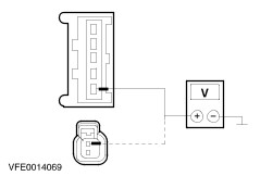
Symptom Chart | Symptom | Possible Sources | Action | | The reversing lamps are inoperative | * Open circuit(s) (e.g. fuses, wiring, park/neutral position (PNP) switch and electrical connectors). | * GO to Pinpoint Test W. | | The individual reversing lamp is inoperative | * Open circuit(s). | * GO to Pinpoint Test X. | | The reversing lamps are on continuously | * Short circuit(s) (e.g. wiring and park/neutral position (PNP) switch). | * GO to Pinpoint Test Y. | Pinpointtests | PINPOINT TEST A : THE REVERSING LAMPS ARE INOPERATIVE | | TEST CONDITIONS | DETAILS/RESULTS/ACTIONS | | A1: DETERMINE MODEL VARIANTS | | | 1 Determine the model variant. | | | Does the vehicle have automatic transmission? Yes No | | A2: CHECK CIRCUIT 15-LG28 (GN/WH) FOR VOLTAGE | | | 1 Ignition switch in position 0. | | | 2 Disconnect PNP switch C862 or C1007 (MY09/99). | | | 3 Ignition switch in position II. | | | 4 Measure the voltage between park/neutral position (PNP) switch, connector C862 or C1007 since MY (09/99), pin 1, circuit 15-LG28 (GN/WH) or (BN/WH), harness side and ground. | | | Is battery voltage indicated? Yes No REPAIR circuit 15-LG28 (GN/WH) or (BN/WH) or 15-DA2 (GN/BU) by using the wiring diagrams. TEST the system for normal operation. | | A3: CHECK CIRCUIT 15-LG9 (GN/BK) FOR OPEN | | | 1 Use a fused (fuse 7.5 A) jumper wire and connect at the park/neutral position (PNP) switch, connector C862 or C1007 since MY (09/99), between pin 1, circuit 15-LG28 (GN/WH) or (BN/WH), and pin 2, circuit 15S-LG9 (GN/BK), harness side. | | | Are the reversing lamps illuminated? Yes INSTALL a new PNP switch. TEST the system for normal operation. No REPAIR circuit 15S-LG9 (GN/BK) by using the wiring diagrams. TEST the system for normal operation. | | A4: CHECK CIRCUIT 15-LG28 (GN/WH) FOR OPEN | | | 1 Ignition switch in position 0. | | | 2 Disconnect TR sensor (C438) (A/T). | | | 3 Ignition switch in position II. | | | 4 Measure the voltage between transmission range (TR) sensor, connector C438, pin 1, circuit 15-LG28 (GN/WH), harness side and ground. | | | Is battery voltage indicated? Yes No REPAIR circuit 15-LG28 (GN/WH) or 15-DA2 (GN/BU) by using the wiring diagrams. TEST the system for normal operation. | | A5: CHECK CIRCUIT 15S-LG9 (GN/BK) FOR OPEN | | | 1 Use a fused (fuse 7.5 A) jumper wire and connect at the TR sensor, connector C438, harness side between pin 1 and pin 3. | | | Are the reversing lamps illuminated? Yes INSTALL a new TR sensor. TEST the system for normal operation. No REPAIR circuit 15S-LG16A (GN/OG) or 15S-LG9 (GN/BK) by using the wiring diagrams. TEST the system for normal operation. | | PINPOINT TEST B : THE INDIVIDUAL REVERSING LAMP IS INOPERATIVE | | TEST CONDITIONS | DETAILS/RESULTS/ACTIONS | | B1: DETERMINE THE INOPERATIVE REVERSING LAMP | | | 1 Ignition switch in position II. | | | 2 Engage reverse gear. | | | Is the right-hand reversing lamp illuminated? Yes No | | B2: CHECK CIRCUIT 15S-LG16A (GN/OG) FOR OPEN | | | 1 Engage reverse gear. | | | 2 Ignition switch in position 0. | | | 3 Disconnect Left-hand combined rear lamp (C446). | | | 4 Ignition switch in position II. | | | 5 Measure the voltage between left-hand combined rear lamp, connector C446, pin 3, circuit 15S-LG16A (GN/OG), harness side and ground. | | | Is battery voltage indicated? Yes INSTALL a new reversing lamp bulb. TEST the system for normal operation. No REPAIR circuit 15S-LG16A (GN/OG) or 15S-LG9 (GN/BK) by using the wiring diagrams. TEST the system for normal operation. | | B3: CHECK CIRCUIT 15S-LG16 (GN/OG) FOR OPEN | | | 1 Ignition switch in position 0. | | | 2 Disconnect Right-hand combined rear lamp (C447). | | | 3 Ignition switch in position II. | | | 4 Engage reverse gear. | | | 5 Measure the voltage between right-hand combined rear lamp, connector C447, pin 3, circuit 15S-LG16 (GN/OG), harness side and ground. | | | Is battery voltage indicated? Yes INSTALL a new reversing lamp bulb. TEST the system for normal operation. No REPAIR circuit 15S-LG16 (GN/OG) by using the wiring diagrams. TEST the system for normal operation. | | PINPOINT TEST C : THE REVERSING LAMPS ARE ON CONTINUOUSLY | | TEST CONDITIONS | DETAILS/RESULTS/ACTIONS | | C1: CHECK CIRCUIT 15S-LG9 (GN/BK) FOR SHORT TO POWER | | | 1 Ignition switch in position 0. | | | 2 Disconnect PNP switch C862, C1007(M/T) or TR sensor C438(A/T). | | | 3 Ignition switch in position II. | | | 4 Check the reversing lamps. | | | Are the reversing lamps illuminated? Yes REPAIR circuit 15S-LG9 (GN/BK), 15S-LG16A (GN/OG) or 15S-LG16 (GN/OG) by using the wiring diagrams. TEST the system for normal operation. No INSTALL a new TR sensor (A/T) or PNP switch (M/T). TEST the system for normal operation. | Component Tests Relay - Measure the resistance between the contact terminals. If the resistance is greater than 10,000 ohms, GO to 2. If not, INSTALL a new relay.
- Connect the relay to the power supply. Switch on the power supply and measure the resistance between the contact terminals. If the resistance is less than 2 ohms, the relay is OK. If not, INSTALL a new relay.
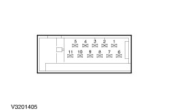
Direction indicator switch | to test | connect ohmmeter to terminals | move switch to these positions | a good switch will indicate | | headlamp flasher | 4 and 2 | neutral | open circuit | | | | main beam | open circuit | | | | headlamp flasher | closed circuit | | main beam | 5 and 2 | neutral | open circuit | | | | main beam | closed circuit | | | | headlamp flasher | open circuit | | dipped beam | 5 and 3 | neutral | closed circuit | | | | main beam | open circuit | | | | headlamp flasher | closed circuit | | LH direction indicator | 49A and 8 | neutral | open circuit | | | | flash left-hand side (no detent) | closed circuit | | | | LH direction indicator | closed circuit | | RH direction indicator | 49A and 9 | neutral | open circuit | | | | flash right-hand side (no detent) | closed circuit | | | | RH direction indicator | closed circuit | | hazard warning | 49 and 11 | neutral | closed circuit | | | | hazard warning | open circuit | | | 49 and 10 | neutral | open circuit | | | | hazard warning | closed circuit | | | 49A and 8 | neutral | open circuit | | | | hazard warning | closed circuit | | | 49A and 9 | neutral | open circuit | | | | hazard warning | closed circuit | | ground | 31 and 7 | every position | closed circuit | Light switch LHD | to test | connect ohmmeter to terminals | move switch to these positions | a good switch will indicate | | headlamp circuit | 11 and 12 | dipped beam | closed circuit | | | | parking lamps | open circuit | | | | neutral | open circuit | | | | parking lamps left-hand side | open circuit | | | | parking lamps right-hand side | open circuit | | instrument illumination | 11 and 3 | dipped beam | closed circuit | | | | parking lamps | closed circuit | | | | neutral | open circuit | | | | parking lamps left-hand side | open circuit | | | | parking lamps right-hand side | open circuit | | licence plate lamps (DRL) | 4 and 14 | dipped beam | open circuit | | | | parking lamps | open circuit | | | | neutral | closed circuit | | | | parking lamps left-hand side | open circuit | | | | parking lamps right-hand side | open circuit | | licence plate lamps | 15 and 14 | dipped beam | closed circuit | | | | parking lamps | closed circuit | | | | neutral | open circuit | | | | parking lamps left-hand side | open circuit | | | | parking lamps right-hand side | open circuit | | right-hand parking lamps (DRL) | 4 and 2 | dipped beam | open circuit | | | | parking lamps | open circuit | | | | neutral | closed circuit | | | | parking lamps left-hand side | open circuit | | | | parking lamps right-hand side | open circuit | | right-hand parking lamps | 15 and 2 | dipped beam | closed circuit | | | | parking lamps | closed circuit | | | | neutral | open circuit | | | | parking lamps left-hand side | open circuit | | | | parking lamps right-hand side | open circuit | | left-hand parking lamps (DRL) | 4 and 13 | dipped beam | open circuit | | | | parking lamps | open circuit | | | | neutral | closed circuit | | | | parking lamps left-hand side | open circuit | | | | parking lamps right-hand side | open circuit | | left-hand parking lamps | 15 and 13 | dipped beam | closed circuit | | | | parking lamps | closed circuit | | | | neutral | open circuit | | | | parking lamps left-hand side | open circuit | | | | parking lamps right-hand side | open circuit | | parking lamps RH | 5 and 2 | dipped beam | closed circuit | | | | parking lamps | closed circuit | | | | neutral | open circuit | | | | parking lamps left-hand side | open circuit | | | | parking lamps right-hand side | open circuit | | fog lamps - front | 8 and 10 | off | open circuit | | | | front fog | closed circuit | | | | rear fog | closed circuit | | fog lamps - rear | 8 and 6 | off | open circuit | | | | front fog | open circuit | | | | rear fog | closed circuit | Light switch RHD | to test | connect ohmmeter to terminals | move switch to these positions | a good switch will indicate | | headlamp circuit | 11 and 12 | dipped beam | closed circuit | | | | parking lamps | open circuit | | | | neutral | open circuit | | | | parking lamps | open circuit | | instrument illumination | 11 and 3 | dipped beam | closed circuit | | | | parking lamps | closed circuit | | | | neutral | open circuit | | | | parking lamps | open circuit | | licence plate lamps (DRL) | 4 and 14 | dipped beam | open circuit | | | | parking lamps | open circuit | | | | neutral | closed circuit | | | | parking lamps | open circuit | | licence plate lamps | 15 and 14 | dipped beam | closed circuit | | | | parking lamps | closed circuit | | | | neutral | open circuit | | | | parking lamps | open circuit | | right-hand parking lamps (DRL) | 4 and 2 | dipped beam | open circuit | | | | parking lamps | open circuit | | | | neutral | closed circuit | | | | parking lamps | open circuit | | right-hand parking lamps | 15 and 2 | dipped beam | closed circuit | | | | parking lamps | closed circuit | | | | neutral | open circuit | | | | parking lamps | open circuit | | left-hand parking lamps (DRL) | 4 and 13 | dipped beam | open circuit | | | | parking lamps | open circuit | | | | neutral | closed circuit | | | | parking lamps | open circuit | | left-hand parking lamps | 15 and 13 | dipped beam | closed circuit | | | | parking lamps | closed circuit | | | | neutral | open circuit | | | | parking lamps | open circuit | | parking lamps | 5 and 13 | dipped beam | open circuit | | | | parking lamps | open circuit | | | | neutral | open circuit | | | | parking lamps | closed circuit | | fog lamps - front | 8 and 10 | off | open circuit | | | | front fog | closed circuit | | | | rear fog | closed circuit | | fog lamps - rear | 8 and 6 | off | open circuit | | | | front fog | open circuit | | | | rear fog | closed circuit | |