| PINPOINT TEST A : THE ALARM SYSTEM DOES NOT OPERATE CORRECTLY |
| TEST CONDITIONS | DETAILS/RESULTS/ACTIONS |
| A1: SELF - TEST INPUTS AND OUTPUTS OF THE CSM |
| | 1 Carry out the CSM self - test. REFER to Self-Test in this section. |
| | Do all of the tested inputs respond correctly? Yes For vehicles with interior scanning, GO to A2. Otherwise, RETRIEVE DTCs If no DTCs, TEST the system for normal operation. No If the CSM does not enter self - test, GO to A5. If the alarm system horn does not sound. GO to A8. If the turn signal lamps do not flash, GO to A9. If no response from the: |
| A2: CHECK INTERIOR SCAN SENSORS |
| | 1 Partially lower the driver door window, then arm the anti - theft system. |
| | 2 Wait for approximately one minute then wave your hand past the driver side scan sensor. |
| | 3 Raise the driver door window. Partially lower the passenger door window, then arm the anti - theft system. |
| | 4 Wait for approximately one minute then wave your hand past the passenger side scan sensor. |
| | Did the alarm go off for each sensor? Yes RETRIEVE DTCs, TEST the system for normal operation. No If driver side scan sensor inoperative, GO to A3. If passenger side scan sensor inoperative, GO to A4. |
| A3: CHECK INOPERATIVE DRIVER SIDE INTERIOR SCAN SENSOR HARNESS |
| | 1 Disconnect Interior Scan Sensor C453. |
| | 2 Disconnect CSM C451c. |
| | 3 Measure the resistance between the interior scan sensor C453 pin 5, circuit 29S - MB10 (OG/YE), harness side and CSM C451c pin 2, circuit 29S - MB10 (OG/YE), harness side. |
| | 4 Measure the resistance between the interior scan sensor C453 pin 4, circuit 31 - MB10 (BK), harness side and CSM C451c pin 6, circuit 31 - MB10 (BK), harness side. |
| | 5 Measure the resistance between the interior scan sensor C453 pin 3, circuit 9 - MB10 (BN), harness side and CSM C451c pin 1, circuit 9 - MB10 (BN), harness side. |
| | 6 Measure the resistance between the interior scan sensor C453 pin 2, circuit 8 - MB10 (WH), harness side and CSM C451c pin 9, circuit 8 - MB10 (WH), harness side. |
| | 7 Measure the resistance between the interior scan sensor C453 pin 1, circuit 7 - MB10 (YE), harness side and CSM C451c pin 5, circuit 7 - MB10 (YE), harness side. |
| | Are the resistances less than 5 ohms? Yes RETRIEVE DTCs. If there are no DTCs, TEST the system for normal operation. If the concern persists, INSTALL a new interior scan sensor. TEST the system for normal operation. No REPAIR or INSTALL a new interior scan sensor harness. TEST the system for normal operation. |
| A4: CHECK INOPERATIVE PASSENGER SIDE INTERIOR SCAN SENSOR HARNESS |
| | 1 Disconnect Interior Scan Sensor C452. |
| | 2 Disconnect CSM C451c. |
| | 3 Measure the resistance between the interior scan sensor C452 pin 5, circuit 29S - MB17 (OG/BU), harness side and CSM C451c pin 3, circuit 29S - MB17 (OG/BU), harness side. |
| | 4 Measure the resistance between the interior scan sensor C452 pin 4, circuit 31 - MB17 (BK), harness side and CSM C451c pin 6, circuit 31 - MB17 (BK), harness side. |
| | 5 Measure the resistance between the interior scan sensor C452 pin 3, circuit 9 - MB17 (BN/RD), harness side and CSM C451c pin 10, circuit 9 - MB17 (BN/RD), harness side. |
| | 6 Measure the resistance between the interior scan sensor C452 pin 2, circuit 8 - MB17 (WH/RD), harness side and CSM C451c pin 8, circuit 8 - MB17 (WH/RD), harness side. |
| | 7 Measure the resistance between the interior scan sensor C452 pin 1, circuit 7 - MB17 (YE/RD), harness side and CSM C451c pin 4, circuit 7 - MB17 (YE/RD), harness side. |
| | Are the resistances less than 5 ohms? Yes RETRIEVE DTCs. If there are no DTCs, TEST the system for normal operation. If the concern persists, INSTALL a new interior scan sensor. TEST the system for normal operation. No REPAIR or INSTALL a new interior scan sensor harness. TEST the system for normal operation. |
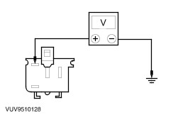
| A5: CHECK HOOD SWITCH SIGNAL TO CSM |
| | 1 Disconnect CSM C451b. |
| | 2 Measure the resistance between the CSM C451b pin 3, circuit 31S - MB7 (BK/YE), harness side and ground. Note the reading with the hood closed and with the hood open. |
| | Is the resistance less than 5 ohms with the hood closed and greater than 10,000 ohms with the hood open? Yes RETRIEVE DTCs. If no DTCs are retrieved, TEST the system for normal operation. If the concern persists, INSTALL a new CSM, REFER to Section 419-10 Multifunction Electronic Modules. TEST the system for normal operation. No |
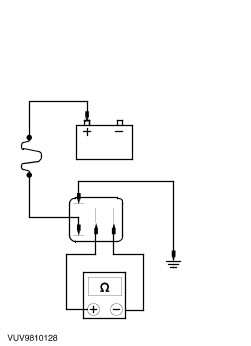
| A6: CHECK HOOD SWITCH |
| | 1 Disconnect Hood Switch C897. |
| | 2 Measure the resistance between the hood switch C897 pin 1 and pin 2. Note the reading with the switch plunger at rest and depressed. |
| | Is the resistance less than 5 ohms with the switch plunger at rest and greater than 10,000 ohms with the switch plunger depressed? Yes No INSTALL a new hood switch. TEST the system for normal operation. |
| A7: CHECK GROUND TO HOOD SWITCH |
| | 1 Measure the resistance between the hood switch C897 pin 2, circuit 31 - MB7 (BK), harness side and ground. |
| | Is the resistance less than 5 ohms? Yes REPAIR circuit 31S - MB7 (BK/YE). TEST the system for normal operation. No REPAIR circuit 31 - MB7 (BK). TEST the system for normal operation. |
| A8: CHECK GROUND SIGNAL TO ALARM SYSTEM HORNN |
| | 1 Disconnect Alarm System Horn C811. |
| | 2 Measure the resistance between the alarm system horn C811 and ground. |
| | Is the resistance less than 5 ohms? Yes REPAIR circuit 49 - MB26 (BU/YE). TEST the system for normal operation. No CLEAN and TIGHTEN the alarm system horn mounting. TEST the system for normal operation. If the concern persists, INSTALL a new alarm system horn. TEST the system for normal operation. |
| A9: CHECK RELAY |
| | 1 Disconnect Anti - Theft Turn Signal Lamp Relay. |
| | 2 Using a jumper wire fused at 5 amps, connect the coil side pin of the anti - theft relay with the battery positive terminal. |
| | 3 Place a jumper wire on the coil side of the anti - theft relay. |
| | 4 Measure the resistance between the switched pins of the anti - theft turn signal lamp relay. Note the reading with an unfused jumper wire connected to ground and not connected to ground. |
| | Is the resistance less than 5 ohms with an unfused jumper wire connected to ground and greater than 10.000 ohms with the unfused jumper wire not connected to ground? Yes No INSTALL a new anti - theft turn signal lamp relay. TEST the system for normal operation. |
| A10: CHECK VOLTAGE TO RH ANTI - THEFT TURN SIGNAL LAMP RELAY |
| | 1 Disconnect RH Anti - Theft Turn Signal Lamp Relay C2107. |
| | 2 Measure the voltage between the RH anti - theft turn signal lamp relay C2107, circuit 29 - MB25 (OG), harness side and ground. |
| | Is the voltage greater than 10 volts? Yes No If fuse F12 is OK, REPAIR circuit 29 - MB25. TEST the system for normal operation. |
| A11: CHECK POWER TO LH SWITCH SIDE OF ANTI - THEFT TURN SIGNAL LAMP RELAY |
| | 1 Disconnect LH Anti - Theft Turn Signal Lamp Relay C2108. |
| | 2 Measure the voltage between the LH anti - theft turn signal lamp relay C2108, circuit 29 - MB23 (OG/WH), harness side and ground. |
| | Is the voltage greater than 10 volts? Yes No REPAIR circuit 29 - MB23. TEST the system for normal operation. |
| A12: CHECK POWER TO LH COIL SIDE OF ANTI - THEFT TURN SIGNAL LAMP RELAY |
| | 1 Measure the voltage between the LH anti - theft turn signal lamp relay C2108, circuit 29 - MB22 (OG/GN), harness side and ground. |
| | Is the voltage greater than 10 volts? Yes No REPAIR circuit 29 - MB22. TEST the system for normal operation. |
| A13: CHECK POWER TO RH COIL SIDE OF ANTI - THEFT TURN SIGNAL LAMP RELAY |
| | 1 Measure the voltage between RH anti - theft turn signal lamp relay C2107, circuit 29 - MB24 (OG/YE), harness side and ground. |
| | Is the voltage greater than 10 volts? Yes No REPAIR circuit 29 - MB24. TEST the system for normal operation. |
| A14: CHECK CIRCUIT TO TURN SIGNAL LAMPS |
| | 1 Measure the resistance between the the RH anti - theft turn signal lamp relay C2107, circuit 49 - MB25 (BU/WH), harness side and ground. |
| | 2 Measure the resistance between the LH anti - theft turn signal lamp relay C2108, circuit 49 - MB23 (BU/OG), harness side and ground. |
| | Is the resistance between 0.5 and 5.0 ohms for each circuit tested? Yes No REPAIR the circuit in question. TEST the system for normal operation. |
| A15: CHECK COIL GROUND TO SIDE OF RELAYS |
| | 1 Measure the resistance between the LH anti - theft relay C2108, circuit 31S - MB22 (BK/RD), harness side and RH anti - theft relay C2107, circuit 31S - MB22 (BK/RD), harness side. |
| | Is the resistance less than 5 ohms? Yes REPAIR circuit 31S - MB24. TEST the system for normal operation. No REPAIR circuit 31S - MB22. TEST the system for normal operation. |
| A16: CHECK DOOR LOCK OPERATION |
| | 1 Operate the door locks using the door lock switch and the door lock cylinder, from both the driver and passenger doors |
| | Do the doors lock and unlock correctly? Yes No |
| A17: CHECK DOOR LOCK SIGNAL TO CSM |
| | 1 Disconnect CSM C451b. |
| | 2 Measure the resistance between the CSM C451b pin 11, (circuit 31S - AA61A for driver side, 31S - AA61 for passenger side) (BK/BU), harness side and ground. Note the reading while locking the driver door and while locking the passenger door. |
| | Is the resistance less than 5 ohms when locking each door? Yes No |
| A18: CHECK DOOR UNLOCK SIGNAL TO CSM |
| | 1 Measure the resistance between the CSM C451b pin 15, (circuit 31S - AA62A for driver side, 31S - AA62 for passenger side) (BK/WH), harness side and ground. Note the reading while unlocking the driver door and while unlocking the passenger door. |
| | Is the resistance less than 5 ohms? Yes CONNECT the electrical connectors and components. TEST the system for normal operation. If the concern persists, INSTALL a new CSM. TEST the system for normal operation. No |
| A19: CHECK LOCK SIGNAL TO DOOR LOCK MOTOR |
| | 1 Disconnect Inoperative Door Lock Motor. |
| | 2 Measure the resistance between the CSM C451b pin 11, (circuit 31S - AA61A for driver side, 31S - AA61 for passenger side) (BK/BU), harness side and inoperative door lock motor pin 5, circuit 31S - AA61 (BK/BU), harness side. |
| | 3 Measure the resistance between the CSM C451b pin 11, (circuit 31S - AA61A for driver side, 31S - AA61 for passenger side) (BK/BU), harness side and ground. |
| | Is the resistance less than 5 ohms between connectors and greater than 10,000 ohms to ground? Yes INSTALL a new door lock motor. TEST the system for normal operation. No REPAIR the circuit. TEST the system for normal operation. |
| A20: CHECK UNLOCK CIRCUIT TO MOTOR |
| | 1 Disconnect Inoperative Door Lock Motor. |
| | 2 Measure the resistance between the CSM C451b pin 15, (circuit 31S - AA62A for driver side, 31S - AA62 for passenger side) (BK/WH), harness side and inoperative door lock motor pin 7, circuit 31S - AA62 (BK/WH), harness side. |
| | 3 Measure the resistance between the CSM C451b pin 15, (circuit 31S - AA62A for driver side, 31S - AA62 for passenger side) (BK/WH), harness side and ground. |
| | Is the resistance less than 5 ohms between the connectors and greater than 10,000 ohms to ground? Yes INSTALL a new door lock motor. TEST the system for normal operation. No REPAIR the circuit. TEST the system for normal operation. |
| A21: CHECK INTERIOR ILLUMINATION |
| | 1 Place the interior lamp switch in the 12 SEC position. Check the operation of the interior illumination from the door that is in question. |
| | Does the interior illumination operate correctly? Yes REPAIR the circuit (for driver side, 31S - MB46 [BK/YE], for passenger side, 31S - MB47 [BK/BU]). TEST the system for normal operation. No |
| A22: CHECK OPERATION OF ANTI - THEFT INHIBIT SWITCH |
| | 1 Disconnect Liftgate Ant - Theft Inhibit Switch C632. |
| | 2 Measure the resistance between the liftgate anti - theft inhibit switch C632 pin 2, circuit 31 - MB27 (BK), harness side and ground. |
| | Is the resistance less than 5 ohms? Yes No REPAIR the circuit. TEST the system for normal operation. |
| A23: CHECK LIFTGATE INHIBIT SWITCH |
| | 1 Measure the resistance between the liftgate anti - theft inhibit switch pin 1 and pin 2. Note the reading with the key unlocking the liftgate and with the key not in the key cylinder. |
| | Is the resistance less than 5 ohms with the key unlocking the liftgate and greater than 10,000 ohms otherwise.? Yes REPAIR circuit 31S - MB27. TEST the system for normal operation. No INSTALL a new liftgate anti - theft inhibit switch. TEST the system for normal operation |
| A24: CHECK INTERIOR ILLUMINATION FROM LIFTGATE |
| | 1 Place the interior lamp in the 12 SEC position. Activate the interior illumination by opening the liftgate |
| | Does the interior illumination operate correctly? Yes REPAIR circuit 31S - MB20 (BK/RD). TEST the system for normal operation. No |