| PINPOINT TEST E : THE BACK WINDOW WILL NOT DEFROST |
NOTE:This symptom covers the complete defrost system which includes the heated outside mirrors. If both heated outside mirrors do not defrost GO to E16. If a single heated outside mirror does not defrost GO to E21. |
| TEST CONDITIONS | DETAILS/RESULTS/ACTIONS |
| E1: CHECK FUSE 29 (30A) |
| | 1 Ignition switch in position 0. |
| | 2 CHECK Fuse 29 (30A). |
| | 3 Check fuse 29 (30A). |
| | Is the fuse OK? Yes No INSTALL a new fuse 29 (30A). Test the system for normal operation. If fuse fails again, GO to E2. |
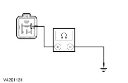
| E2: CHECK FOR SHORT TO GROUND ON CIRCUIT 14S - HB19 (VT/BU) |
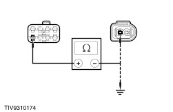
| | 1 Disconnect Central timer module C368. |
| | 2 Disconnect Back window defroster C1851a. |
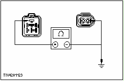
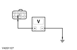
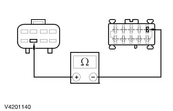
| | 3 Measure the resistance between the back window defroster C1851a, circuit 14S - HB19 (VT/BU), and ground. |
| | Is the resistance greater than 10,000 ohms? Yes No REPAIR circuit 14S - HB19 (VT/BU). TEST the system for normal operation. |
| E3: CHECK CIRCUIT 14S - HB2 (VT/BU) FOR SHORT TO GROUND |
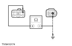
| | 1 Disconnect Central timer module C364. |
| | 2 Disconnect Back window defroster switch C437. |
| | 3 Measure the resistance between the back window defroster switch C437 pin 6, circuit 14S - HB2 (VT/BU) and ground. |
| | Is the resistance greater than 10,000 ohms? Yes No REPAIR circuit 14S - HB2 (VT/BU). TEST the system for normal operation. |
| E4: CHECK THE CENTRAL TIMER MODULE FOR SHORT TO GROUND |
| | 1 Connect Central timer module C368. |
| | 2 Connect Central timer module C364. |
| | 3 Measure the resistance between the back window defroster C1851a, circuit 14S - HB19 (VT/BU), and ground; and between the back window defroster switch C437 pin 6, circuit 14S - HB2 (VT/BU) and ground. |
| | Are the resistances greater than 10,000 ohms? Yes INSTALL a new back window defroster switch. TEST the system for normal operation. No INSTALL a new central timer module. TEST the system for normal operation. |
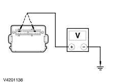
| E5: CHECK CIRCUIT 30 - DA4 (RD) FOR VOLTAGE |
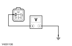
| | 1 Disconnect Central timer module C370. |
| | 2 Measure the voltage between the central timer module C370 pin 2, circuit 30 - DA4 (RD) and ground. |
| | Is the voltage greater than 10 volts? Yes No REPAIR circuit 30 - DA4 (RD). TEST the system for normal operation. |
| E6: CHECK FOR VOLTAGE TO THE BACK WINDOW DEFROSTER RELAY |
| | 1 Connect Central timer module C370. |
| | 2 Disconnect Back window defroster relay C56. |
| | 3 Measure the voltage between the back window defroster relay C56 pin 3, and ground; and between the back window defroster relay C56 pin 1 and ground. |
| | Are the voltages greater than 10 volts? Yes No REPAIR the central timer module. TEST the system for normal operation. |
| E7: CHECK THE BACK WINDOW DEFROSTER RELAY |
| | 1 Test the back window defroster relay. For additional information, refer to the wiring diagram. |
| | Is the back window defroster relay OK? Yes No INSTALL a new back window defroster relay. TEST the system for normal operation. |
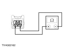
| E8: CHECK THE BACK WINDOW DEFROSTER SWITCH |
| | 1 Test the back window defroster switch. For additional information, refer to the wiring diagram. |
| | Is the back window defroster switch OK? Yes No INSTALL a new back window defroster switch. TEST the system for normal operation. |
| E9: CHECK FOR OPEN ON CIRCUIT 31 - HB22 (BK) |
| | 1 Disconnect Back window defroster switch C437. |
| | 2 Measure the resistance between the back window defroster switch C437 pin 1, circuit 31 - HB22 (BK) and ground. |
| | Is the resistance less than 5 ohms? Yes No REPAIR circuit 31 - HB22 (BK). TEST the system for normal operation. |
| E10: CHECK FOR VOLTAGE TO THE CENTRAL TIMER MODULE |
| | 1 Connect Back window defroster relay C56. |
| | 2 Disconnect Central timer module C23. |
| | 3 Measure the voltage between the central timer module C23 pin 18 and ground; and between central timer module C23 pin 12 and ground. |
| | Are the voltages greater than 10 volts? Yes No INSTALL a new central timer module. TEST the system for normal operation. |
| E11: CHECK THE CENTRAL TIMER MODULE GROUND INPUT FROM THE BACK WINDOW DEFROST SWITCH |
| | 1 Connect Back window defroster switch C437. |
| | 2 Depress the back window defroster switch. |
| | 3 Measure the voltage between the central timer module C23 pin 4 and the central timer module C23 pin 18. |
| | Is the voltage greater than 10 volts? Yes No |
| E12: CHECK CIRCUIT 14S HB29 (VT/WH) FOR OPEN |
| | 1 Disconnect Back window defroster switch C437. |
| | 2 Disconnect Central timer module C364. |
| | 3 Measure the resistance between the back window defroster switch C437 pin 2 and the central timer module C364 pin 5, circuit 14S HB29 (BK/WH). |
| | Is the resistance less than 5 ohms? Yes No REPAIR circuit 14S - HB29 (BK/WH). TEST the system for normal operation. |
| E13: CHECK THE CENTRAL TIMER MODULE FOR OPEN AND SHORT TO GROUND BETWEEN CENTRAL TIMER MODULE AND BACK WINDOW DEFROSTER SWITCH |
| | 1 Ignition switch in position 0. |
| | 2 Measure the resistance between the central timer module C364 pin 5 and the central timer module C23 pin 4; and between the central timer module C634 pin 5 and ground. |
| | Is the resistance less than 5 ohms between the two connectors and greater than 10,000 ohms between the central timer module and ground? Yes No INSTALL a new central timer module. TEST the system for normal operation. |
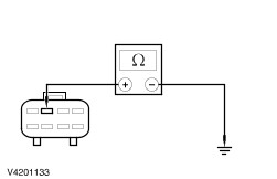
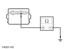
| E14: CHECK THE BACK WINDOW DEFROSTER GROUND - CIRCUIT 31 - HB19 (BK) |
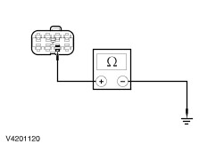
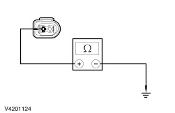
| | 1 Disconnect Back window defroster C1851b. |
| | 2 Measure the resistance between the back window defroster C1851b, circuit 31 - HB19 (BK) and ground. |
| | Is the resistance less than 5 ohms? Yes No REPAIR circuit 31 - HB19 (BK). TEST the system for normal operation. |
| E15: CHECK CIRCUIT 14S - HB19 (VT/BU) FOR VOLTAGE |
| | 1 Connect Back window defroster switch C437. |
| | 2 Connect Central timer module C23. |
| | 3 Connect Central timer module C364. |
| | 4 Disconnect Back window defroster C1851a. |
| | 5 Ignition switch in position II. |
| | 6 Operate the back window defroster switch to the on position. |
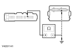
| | 7 Measure the voltage between the back window defroster C1851a, circuit 14S - HB19 (VT/BU) and ground. |
| | Is the voltage greater than 10 volts? Yes INSTALL a new heated back window. REFER to Window Glass - Liftgate in this section. Test the system for normal operation. No REPAIR circuit 14S - HB19 (VT/BU). TEST the system for normal operation. |
| E16: CHECK THE HEATED BACK WINDOW OPERATION |
| | 1 Ignition switch in position III. |
| | 2 CHECK the heated back window operation. |
| | Does the heated back window switch illuminate and the heated back window function? Yes No |
| E17: CHECK FUSE 19 (7.5A) |
| | 1 Ignition switch in position 0. |
| | 2 Disconnect Fuse 19 (7.5A). |
| | 3 CHECK Fuse 19 (7.5A). |
| | Is the fuse OK? Yes No INSTALL a new fuse. TEST the system for normal operation. |
| E18: CHECK SUPPLY CIRCUIT 14S - HB1 |
| | 1 Connect Fuse 19 (7.5A). |
| | 2 Disconnect CJB C - 336. |
| | 3 Ignition switch in position III. |
| | 4 Operate the back window defroster switch. |
| | 5 MEASURE the voltage at the CJB connector C336 pin 7, circuit 14S - HB1 (VT/BU) and ground. |
| | Is the voltage greater that 10 volts? Yes No INSTALL a new central timer module (CJB). TEST the system for normal operation. |
| E19: CHECK CONTINUITY OF CIRCUIT 14S - HB1 AND 14S - HB37 |
NOTE:There is a solder joint between the CJB and power mirrors |
| | 1 Disconnect Power mirror C574. |
| | 2 Disconnect Power mirror C336. |
| | 3 MEASURE the resistance between the CJB connector C336 pin, circuit 14S - HB1 and: - C336 pin 1, circuit 14S - HB37 (VT/BK)
- C574 pin 1, circuit 14S - HB37 (VT/BK)
|
| | Is the resistance less than 5 ohms? Yes No REPAIR circuit 14S - HB1 (VT/BU) and 14S - HB37 (VT/BK). TEST the system for normal operation. |
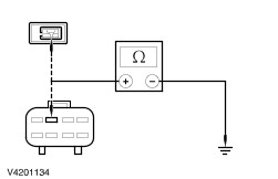
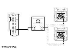
| E20: CHECK THE HEATED MIRROR ELEMENT |
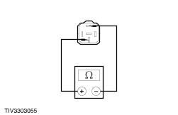
| | 1 Disconnect Heated mirror element. |
| | 2 MEASURE the resistance of the heated mirror element. |
| | Is the resistance 8 - 9 ohms? Yes REPAIR the mirror head sub - loom. TEST the system for normal operation. No INSTALL a new heated mirror glass. TEST The system for normal operation. |
| E21: CHECK THE POWER SUPPLY TO HEATED MIRROR |
| | 1 Disconnect C574. |
| | 2 Ignition switch in position III. |
| | 3 Operate the back window defroster switch. |
| | 4 CHECK the voltage at the: - Left - hand power mirror connector C574 between pin 1, circuit 14S - HB37 (VT/BK) harness side and ground.
- Right - hand power mirror connector C - 574 between pin 1, circuit 14S - HB37 (VT/BK) harness side and ground.
|
| | Is the voltage greater than 10 volts? Yes No REPAIR circuit 14S - HB1 (VT/BU and 14S - HB 28 (VT/OG). TEST the system for normal operation. |
| E22: CHECK GROUND CIRCUITS 31 - HB37 |
| | 1 Ignition switch in position 0. |
| | 2 MEASURE the resistance at the: - Left - hand power mirror connector C574, pin 3, circuit 31 - HB37 (BK) harness side and ground.
- Right - hand power mirror connector C - 574 pin 3, circuit 31 - HB37 (BK) harness side and ground.
|
| | Is the resistance less than 5 ohms? Yes No REPAIR circuit 31 - HB37 (BK). TEST the system for normal operation. |
| E23: CHECK THE HEATED MIRROR HEAD CIRCUIT |
| | 1 MEASURE the resistance between the power mirror head connector: - Left - hand C574 pin 1, circuit 14S - HB1 (VT/BU) and pin 3, circuit 31 - HB 37 (BK) harness side.
- Right - hand C574 pin 1 circuit 14S - HB28 (VT/OG) and pin 3, circuit 31 - HB37 (BK harness side.
|
| | Is the resistance 8 - 9 ohms? Yes Verify the customer concern. No |
| E24: CHECK THE HEATED MIRROR ELEMENT |
| | 1 Disconnect . |
| | 2 MEASURE the resistance of the heated mirror element. |
| | Is the resistance 8 - 9 ohms? Yes REPAIR the mirror head sub - loom. TEST the system for normal operation. No INSTALL a new heated mirror glass. TEST the system for normal operation. |