| PINPOINT TEST E : THE DEFROST SYSTEM IS INOPERATIVE |
NOTE:This symptom covers the defrost system for the heated rear window, the heated exterior mirrors and the heated windshield. For the heated rear window and the heated exterior mirrors GO to E1 for the heated windshield GO to E15. |
| TEST CONDITIONS | DETAILS/RESULTS/ACTIONS |
| E1: CARRY OUT THE CENTRAL TIMER MODULE INPUT DIAGNOSTIC TEST |
| | 1 Carry out the central timer module input diagnostic test. REFER to Section 413-09 Warning Devices. Operate the heated rear window control switch. |
| | Is the self test OK? Yes No |
| E2: CARRY OUT THE CENTRAL TIMER MODULE OUTPUT DIAGNOSTIC TEST |
| | 1 Carry out the central timer module output diagnostic test. REFER to Section 413-09 Warning Devices. Operate the heated rear window control switch three or four times. |
| | Does the heated rear window relay click? Yes No |
| E3: CHECK THE HEATED REAR WINDOW CONTROL SWITCH LED |
| | 1 Ignition switch in position II. |
| | 2 Operate the heated rear window control switch. |
| | Does the LED illuminate? Yes No |
| E4: CHECK THE CENTRAL JUNCTION BOX FUSE 29 (30A) |
| | 1 Ignition switch in position 0. |
| | 2 CHECK Fuse 29 (30A). |
| | 3 Check the central junction box fuse 29 (30A). |
| | Is the fuse OK? Yes No INSTALL a new fuse. TEST the system for normal operation. If the fuse fails again, CHECK circuit 15S-HB19 (GN/BU) for a short to ground. |
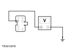
| E5: CHECK FOR VOLTAGE TO THE HEATED REAR WINDOW |
| | 1 Ignition switch in position II. |
| | 2 Disconnect Heated Rear Window C1891a. |
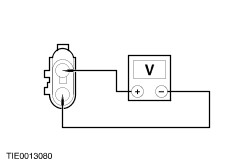
| | 3 Operate the heated rear window control switch. Measure the voltage between the heated rear window C1891a, circuit 15S-HB19 (GN/BU) and ground. |
| | Is the voltage greater than 10 volts? Yes No REPAIR circuit 15S-HB19 (GN/BU). TEST the system for normal operation. |
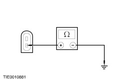
| E6: CHECK THE HEATED REAR WINDOW GROUND CIRCUIT |
| | 1 Ignition switch in position 0. |
| | 2 Connect Heated Rear Window C1891a. |
| | 3 Disconnect Heated Rear Window C1891b. |
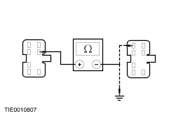
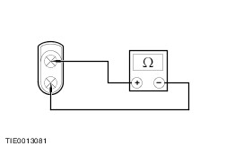
| | 4 Measure the resistance between the heated rear window C1891b, circuit 31-HB19 (BK) and ground. |
| | Is the resistance less than 5 ohms? Yes INSTALL a new heated rear window. TEST the system for normal operation. No REPAIR circuit 31-HB19 (BK). TEST the system for normal operation. |
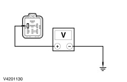
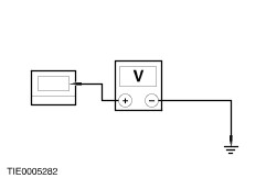
| E7: CHECK FOR VOLTAGE TO THE HEATED REAR WINDOW RELAY |
| | 1 Ignition switch in position 0. |
| | 2 Disconnect Heated Rear Window Relay. |
| | 3 Measure the voltage between the heated rear window relay C56 pin 2, circuit 30-DA4 (RD) and ground. |
| | Is the voltage greater than 10 volts? Yes No REPAIR circuit 30-DA4 (RD). TEST the system for normal operation. |
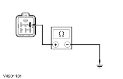
| E8: CHECK THE HEATED REAR WINDOW RELAY |
| | 1 Carry out the component test for the heated rear window relay. For additional information, refer to the Wiring Diagram. |
| | Is the heated rear window relay OK? Yes No INSTALL a new heated rear window relay. TEST the system for normal operation. |
| E9: CHECK FOR VOLTAGE TO THE CENTRAL TIMER MODULE |
| | 1 Connect Heated Rear Window Relay. |
| | 2 Disconnect Central Timer Module. |
| | 3 Ignition switch in position II. |
| | 4 Measure the voltage between the central timer module (CTM) pin 18 and ground and the CTM pin 12 and ground. |
| | Are the voltages greater than 10 volts? Yes INSTALL a new CTM. TEST the system for normal operation. No INSTALL a new central junction box. TEST the system for normal operation. |
| E10: CHECK THE CENTRAL TIMER MODULE GROUND CIRCUIT |
| | 1 Ignition switch in position 0. |
| | 2 Disconnect Central Timer Module. |
| | 3 Operate the heated rear window control switch and keep the button pressed. Measure the resistance between the central timer module (CTM) pin 4 and ground. |
| | Is the resistance less than 5 ohms? Yes INSTALL a new CTM. TEST the system for normal operation. No |
| E11: CHECK THE HEATED REAR WINDOW CONTROL SWITCH GROUND CIRCUIT |
| | 1 Disconnect Heated Rear Window Control Switch. |
| | 2 Measure the resistance between the heated rear window control switch C437 pin 1, circuit 31-HB22 (BK) and ground. |
| | Is the resistance less than 5 ohms? Yes INSTALL a new heated rear window control switch. TEST the system for normal operation. No REPAIR circuit 31-HB22 (BK). TEST the system for normal operation. |
| E12: CHECK THE CENTRAL JUNCTION BOX FUSE 19 (7.5A) |
| | 1 Ignition switch in position 0. |
| | 2 CHECK Fuse 19 (7.5A). |
| | 3 Check the central junction box fuse19 (7.5A). |
| | Is the fuse OK? Yes No INSTALL a new fuse. TEST the system for normal operation. If the fuse fails again, REPAIR circuit 15S-HB1 (GN/BU). |
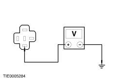
| E13: CHECK FOR VOLTAGE AT THE HEATED EXTERIOR MIRRORS |
| | 1 Disconnect Inoperative Heated Exterior Mirror. |
| | 2 Ignition switch in position II. |
| | 3 Operate the heated rear window control switch. Measure the voltage between the inoperative heated exterior mirror connector and ground; - C807 pin 1 circuit 15S-HB28 (GN/OG) or 15S-HB37 (GN/BK) driver side (RHD); or
- C807 pin 1, circuit 15S-HB37 (GN/BK) or 15S-HB15 (GN/BK) driver side (LHD); or
- C71 pin 1, circuit 15S-HB37 (GN/BK) or 15S-HB15 (GN/BK) passenger side (RHD); or
- C71 pin 1, circuit 15S-HB28 (GN/OG) or 15S-HB37 (GN/BK) passenger side (LHD).
|
| | Is the voltage greater than 10 volts? Yes No REPAIR circuit 15S-HB28 (GN/OG); or 15S-HB37 (GN/BK) or 15S-HB15 (GN/BK). TEST the system for normal operation. |
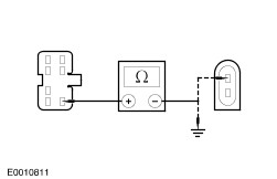
| E14: CHECK THE INOPERATIVE HEATED EXTERIOR MIRROR GROUND CIRCUIT |
| | 1 Ignition switch in position 0. |
| | 2 Measure the resistance between the inoperative heated exterior mirror connector and ground. - C807 pin 3, circuit 31-HB37 (BK) (driver side); or
- C71 pin 3, circuit 31-HB37 (BK) (passenger side).
|
| | Is the resistance less than 5 ohms? Yes INSTALL a new heated exterior mirror glass(es). TEST the system for normal operation. No REPAIR circuit 31-HB37 (BK). TEST the system for normal operation. |
| E15: CHECK THE OPERATION OF THE HEATED WINDSHIELD RELAY |
| | 1 Ignition switch in position II. |
| | 2 With the engine running, operate the heated windshield control switch. |
| | Does the relay click? Yes No |
| E16: CHECK THE BATTERY JUNCTION BOX FUSE 46 (30A) |
| | 1 Ignition switch in position 0. |
| | 2 CHECK Fuse 46 (30A). |
| | 3 Check the battery junction box fuse 46 (30A). |
| | Is the fuse OK? Yes No INSTALL a new fuse. TEST the system for normal operation. If the fuse fails again, REPAIR circuit 15S-DA2 (GN/BU). |
| E17: CHECK THE BATTERY JUNCTION BOX FUSE 47 (30A) |
| | 1 CHECK Fuse 47 (30A). |
| | 2 Check the battery junction box fuse 47 (30A). |
| | Is the fuse OK? Yes No INSTALL a new fuse. TEST the system for normal operation. If the fuse fails again, REPAIR circuit 15S-HB2 (GN/YE). |
| E18: CHECK FOR VOLTAGE TO THE HEATED WINDSHIELD LEFT-HAND ELEMENT |
| | 1 Disconnect Heated Windshield Left-hand Element C634. |
| | 2 Ignition switch in position II. |
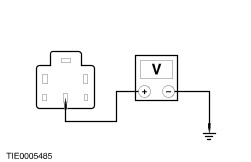
| | 3 With the engine running, operate the heated windshield control switch. Measure the voltage between the heated windshield left-hand element C634 pin 1, circuit 15S-HB12 (GN/YE) and ground. |
| | Is the voltage greater than 10 volts? Yes No REPAIR circuit 15S-HB12 (GN/YE). TEST the system for normal operation. |
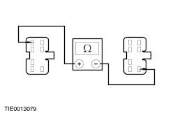
| E19: CHECK THE HEATED WINDSHIELD LEFT-HAND ELEMENT GROUND CIRCUIT |
| | 1 With the engine running, operate the heated windshield control switch. Measure the voltage between the heated windshield left-hand element C634 pin 1, circuit 15S-HB12 (GN/YE) and the heated windshield left-hand element C634 pin 2, circuit 31-HB12 (BK). |
| | Is the voltage greater than 10 volts? Yes No REPAIR circuit 31-HB12 (BK). TEST the system for normal operation. |
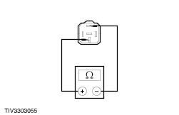
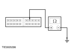
| E20: CHECK THE HEATED WINDSHIELD LEFT-HAND ELEMENT FOR CONTINUITY |
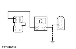
| | 1 Ignition switch in position 0. |
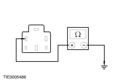
| | 2 Measure the resistance between the heated windshield left-hand element C634 pin 1 (component side) and the heated windshield left-hand element C634 pin 2 (component side). |
| | Is the resistance less than 5 ohms? Yes No INSTALL a new heated windshield. TEST the system for normal operation. |
| E21: CHECK FOR VOLTAGE TO THE HEATED WINDSHIELD RIGHT-HAND ELEMENT |
| | 1 Connect Heated Windshield Left-hand Element C634. |
| | 2 Disconnect Heated Windshield Right-hand Element C635. |
| | 3 Ignition switch in position II. |
| | 4 With the engine running, operate the heated windshield control switch. Measure the voltage between the heated windshield right-hand element C635 pin 1, circuit 15S-HB25 (GN/BU) and ground. |
| | Is the voltage greater than 10 volts? Yes No REPAIR circuit 15S-HB25 (GN/BU). TEST the system for normal operation. |
| E22: CHECK THE HEATED WINDSHIELD RIGHT-HAND ELEMENT GROUND CIRCUIT |
| | 1 Measure the voltage between the heated windshield right-hand element C635 pin 1, circuit 15S-HB25 (GN/BU) and the heated windshield right-hand element C635 pin2, circuit 31-HB25 (BK). |
| | Is the voltage greater than 10 volts? Yes No REPAIR circuit 31-HB25 (BK). TEST the system for normal operation. |
| E23: CHECK THE HEATED WINDSHIELD RIGHT-HAND ELEMENT FOR CONTINUITY |
| | 1 Ignition switch in position 0. |
| | 2 Measure the resistance between the heated windshield right-hand element C635 pin 1 (component side) and the heated windshield right-hand element C635 pin2 (component side). |
| | Is the resistance less than 5 ohms? Yes VERIFY the customer concern. No INSTALL a new heated windshield. TEST the system for normal operation. |
| E24: CHECK FOR VOLTAGE TO THE HEATED WINDSHIELD RELAY |
| | 1 Ignition switch in position 0. |
| | 2 Disconnect Heated Windshield Relay. |
| | 3 Measure the voltage between the heated windshield relay C433 pin 3, circuit 30-HB11 (RD) and ground. |
| | Is the voltage greater than 10 volts? Yes No REPAIR circuit 30-HB11 (RD). TEST the system for normal operation. |
| E25: CHECK THE HEATED WINDSHIELD RELAY |
| | 1 Carry out the component test for the heated windshield relay. For additional information, refer to the Wiring Diagram. |
| | Is the heated windshield relay OK? Yes No INSTALL a new heated windshield relay. TEST the system for normal operation. |
| E26: CHECK FOR VOLTAGE TO THE HEATED WINDSHIELD RELAY FROM THE ENGINE RUN RELAY |
| | 1 Ignition switch in position II. |
| | 2 With the engine running, measure the voltage between the battery junction box heated windshield relay C433 pin 1, circuit 15S-BA9 (GN/BK) and ground. |
| | Is the voltage greater than 10 volts? Yes No REPAIR the engine run circuit. For additional information, refer to the Wiring Diagram. TEST the system for normal operation. |
| E27: CHECK THE HEATED WINDSHIELD GROUND CIRCUIT |
| | 1 Ignition switch in position 0. |
| | 2 Operate the heated windshield control switch and keep the button pressed. Measure the resistance between the heated windshield relay C433 pin 2, circuit 9S-HB9 (BN/WH) and ground. |
| | Is the resistance less than 5 ohms? Yes VERIFY the customer concern. No |
| E28: CHECK THE HEATED WINDSHIELD CONTROL SWITCH GROUND CIRCUIT |
| | 1 Disconnect Heated Windshield Control Switch C631. |
| | 2 Measure the resistance between the heated windshield control switch C631 pin 1, circuit 31-HB9 (BK) and ground. |
| | Is the resistance less than 5 ohms? Yes INSTALL a new heated windshield control switch. TEST the system for normal operation. No REPAIR circuit 31-HB9 (BK). TEST the system for normal operation. |