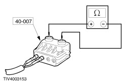
| Diagnosis and Testing Refer to Wiring Diagrams Section 501-20b, for schematic and connector information. Special Tool(s) | | Simulator, Air Bag 418-037 (40-001) | | | Simulator Air Bag/Pyrotechnic Safety Belt 418-047A (40-004A) | | | Simulator, Side Air Bag 418-133 (40-009) | | | Test and Deployment Lead, Air Bag/Pyrotechnic Safety Belt 418-5055 (40-007A) | | | Test and Deployment Lead – Driver Air Bag 418-056 (40-007-01) | | | Test and Deployment Lead – Passenger Air Bag 418-057 (40-007-02) | General Equipment Diagnosing Customer Concerns Without Hard DTCs/LFCs WARNING:The battery back up power supply must be depleted before any work is carried out on the supplemental restraint system. Wait at least one minute after disconnecting the battery ground cable. Failure to follow this instruction may result in personal injury. NOTE:Following the pinpoint tests when a diagnostic trouble code/lamp fault code (DTC/LFC) is not present, will result in needless replacement of air bag system components and repeat repairs. Speak with the customer to determine if a particular set of conditions must be met in order for a fault to occur. If a LFC is reported by the customer but is not present when the vehicle comes in for repair, pinpoint test diagnostics cannot be used. Instruct the customer on how to count an LFC. Diagnosing Customer Concerns with Hard DTCs/LFCs WARNING:Do not use substitute air bag simulators when working on the supplemental restraint system. Use only the appropriate tool. Failure to follow these instructions may result in personal injury. Most air bag system diagnostic procedures require the use of system deactivation and system reactivation procedures. These procedures require the air bag module(s) and safety belt buckle pretensioners to be disconnected from the SRS, thereby removing the risk of air bag deployment while diagnostics are carried out. Air bag simulators are required to carry out diagnosis and testing of the air bag system. The simulator contains a resistor, used to simulate an air bag module connection to the system. It is not acceptable to short-circuit the air bag module connections with a 0 ohm jumper wire. If a 0 ohm jumper wire is used to short-circuit the air bag module connections, an LFC will be displayed and a DTC logged by the air bag control module. Deactivation WARNING:The back up power supply must be depleted, before any work is carried out on the supplemental restraint system. Wait at least one minute after disconnecting the battery ground cable. Failure to follow this instruction may cause personal injury. - Wait at least one minute for the backup power supply energy in the Air Bag Control Module to deplete its stored energy.
WARNING:Place the air bag module on a ground wired bench, with the trim cover facing up to avoid accidental deployment. Failure to follow this instruction may result in personal injury. - Connect the driver air bag simulator to the wiring harness in place of the driver air bag module at the top of the steering column.
- Connect the passenger air bag simulator to the wiring harness in place of the passenger air bag module.
- If equipped, disconnect the driver side air bag module underseat connector.
- Connect the driver side air bag module simulator to the underseat floor harness in place of the side air bag module connector.
- If equipped, disconnect the passenger side air bag module underseat connector.
- Connect the passenger side air bag module simulator to the underseat floor harness in place of the side air bag module connector.
Reactivation WARNING:The air bag simulators must be removed and the air bag modules reconnected when reactivated to avoid non-deployment in a collision. Failure to follow this instruction may result in personal injury. - Wait at least one minute for the backup power supply in the air bag control module to deplete its stored energy.
- Remove the air bag simulator from the wiring harness at the top of the steering column.
- Remove the passenger air bag simulator from the passenger air bag module wiring harness.
- Remove the driver side air bag simulator from the driver side air bag underseat connector.
- Connect and install the driver side air bag module.
REFER to Side Air Bag Module in this section.
- Remove the passenger side air bag simulator from the passenger side air bag underseat connector.
- Connect and install the passenger side air bag module.
REFER to Side Air Bag Module in this section.
Glossary Air Bag Simulator Air bag simulators are used to simulate air bag module connections to the system. Deactivate the System Deactivate the system means to carry out the deactivation procedure. REFER to Deactivation in this section. Prove Out the System The air bag warning indicator will illuminate for approximately five seconds. If a fault is detected the indicator will: - fail to illuminate
- illuminate continuously
- flash
Reactivate the System Reactivate the system means to carry out the reactivation procedure. REFER to Reactivation in this section. Principles of Operation Supplemental Restraint System (SRS) Operation The supplemental restraint system for Cougar, is the European derived single point sensing system, with remote side impact crash sensors, for vehicles equipped with side air bags. Single point sensing has been used in Europe since the introduction of Mondeo in 1993. In the event of a severe frontal or three-quarter frontal impact, in excess of a predetermined limit, the driver and passenger front air bag(s) will deploy. In the event of a severe full side impact, in excess of a predetermined limit, either the driver or passenger side air bag will deploy. Air bag deployment will only occur, in the event of a severe collision when the ignition key is in the RUN position. Air Bag Control Module The air bag control module is mounted vertically, to facilitate impact sensing along the longitudinal axis. The air bag control module retains full control of the whole system. Providing continual system checks and full diagnostic capabilities, the non-volatile memory stores the fault codes, which are down loaded through the data link connector (DLC) to WDS. A visual warning indicator which is housed within the instrument cluster, is illuminated when the ignition is switched ON for approximately five seconds then goes out. If a fault occurs the warning indicator, depending on the nature of the fault, begins to flash or illuminates continuously. In the event of a failure in the vehicle power supply during or after an accident, the air bag control module provides an auxiliary power supply sufficient to deploy the air bag(s) for a minimum of 150mS. The back up power supply is discharged by the air bag control module within 60 seconds of the battery ground cable being disconnected. Thus making sure the supplemental restraint system remains operational. The air bag control module contains a micro-controller to evaluate and process impact data and two sensors. An electronic accelerometer, which converts the actual acceleration and deceleration force, along the vehicles longitudinal axis into electrical signals, and an electro-mechanical safing sensor which measures deceleration only. Provided both these sensors sense an impact in excess of a predetermined limit, the safing sensor will close the circuit to deploy the frontal air bags. The safing sensor retains the control function to prevent unintentional deployment of the frontal air bags. Side Impact Crash Sensor To facilitate remote lateral impact sensing, the side impact crash sensors are mounted on to the floor pan on either side of the vehicle. Each side impact crash sensor contains a micro-controller which processes signals from two accelerometers within the sensor. In the event of an impact in excess of a predetermined limit, the side impact crash sensor processes the side impact data and initiates a deployment request to the air bag control module. The air bag control module processes this request against stored data, to deploy the side air bag on the side the deployment request was initiated. The air bag control module retains control of the side air bags. Air Bag Warning Indicator The air bag warning indicator is incorporated into the instrument cluster, together with the automatic detach detect (ADD) circuit. The air bag warning indicator comes on for 3-5 seconds at key ON. If the system self-tests OK the indicator goes out, if a fault is detected the indicator will flash, illuminate continually from key ON or not illuminate at all, depending on the nature of the fault. The ADD circuit is designed to illuminate the air bag warning indicator continuously, if the air bag control module circuit is broken, either by loss of power or ground supply. Diagnostic evaluation of the supplemental restraints system can be made through the DLC and WDS to establish the nature of the fault. Once the DTC is known the appropriate course of action can be selected from the Symptom Chart. Inspection and Verification - Verify the customer concern.
- Visually inspect for obvious signs of mechanical or electrical damage.
Visual Inspection Chart | Mechanical | Electrical | | | - Fuse(s)
- Electrical connector(s)
- Circuit(s)
- Wiring harness
- Air bag module(s)
| - If an obvious cause for an observed or reported concern is found, correct the cause (if possible) before proceeding to the next step.
- If the cause is not visually evident, check the LFC. Connect WDS to the DLC.
- Retrieve the DTCs, refer to the Symptom Chart
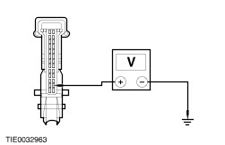
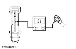
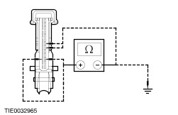
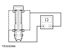
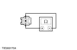
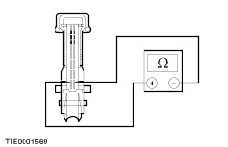
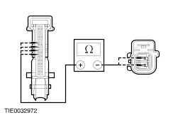
Air Bag Control Module Parameter Identification (PID) Index | PID | Description | Expected Value(s) | | CCNT | Number of Continuous DTCs in Module | Number (1 to 16) | | D_ABAGR | Driver Front Air Bag Resistance | 2.0 to 4.1 Ohms | | P_ABAGR | Passenger Front Air Bag Resistance | 1.8 to 2.2 Ohms | | D_ABAG2 | Driver Side Impact Air Bag Resistance | 1.8 to 2.2 Ohms | | P_ABAG2 | Passenger Side Impact Air Bag Resistance | 1.8 to 2.2 Ohms | | VBAT Air Bag Control Module | Battery Voltage | 9 to 16 Volts | Air Bag Control Module Active Command Index | Active Command | Display | Action | | AIR BAG WARNING LAMP | WARNING | ON, OFF | Symptom Chart Symptom Chart | Symptom | Possible Sources | Action | | No communication with the module | * DLC circuit. * Air bag control module. * Circuit(s). | * | | DTC B1342: Air bag control module is defective. Air bag warning indicator ON all the time | * Air bag control module. | * INSTALL a new air bag control module. REFER to Air Bag Control Module in this section. REPEAT the self-test, CLEAR the DTCs | | DTC B1231: Longitudinal acceleration threshold exceeded. Air bag warning indicator ON all the time | * Crash data memory full. | * Data cannot be cleared with WDS. INSTALL a new air bag control module. REFER to Air Bag Control Module in this section. REPEAT the self-test, CLEAR the DTCs. | | DTC B1870: Air bag warning indicator short to ground or short to battery. | * Instrument cluster. * Circuit. | * | | DTC B1318: Battery voltage low. Air bag warning indicator ON all the time. | * Battery. * Charging system. * Circuit. | * | | DTC B1887: Driver Air bag short to ground or short to battery. Air bag warning indicator three flash cycle. | * Driver air bag module. * Air bag sliding contact. * Circuit. | * | | DTC B1888: Passenger air bag short to battery or short to ground. Air bag warning indicator three flash cycle. | * Passenger air bag module. * Circuit. | * | | DTC B1993: Driver side air bag short to battery or short to ground or resistance high or low. Air bag warning indicator five flash cycle | * Driver air bag module. * Circuit. | * | | DTC B1997: Passenger side air bag short to battery or short to ground or resistance high or low. Air bag warning indicator six flash cycle | * Passenger air bag module. * Circuit. | * | | DTC B1932: Driver air bag open circuit or high resistance. Air bag warning indicator one flash cycle | * Driver air bag module. * Air bag sliding contact. * Circuit. | * | | DTC B1933: Passenger air bag open circuit or high resistance. Air bag warning indicator two flash cycle. | * Passenger air bag module. * Circuit. | * | | DTC: B1934: Driver air bag circuit low resistance. Air bag warning indicator one flash cycle. | * Driver air bag module. * Air bag sliding contact. * Circuit. | * | | DTC B1935: Passenger air bag circuit low resistance. Air bag warning indicator two flash cycle. | * Passenger air bag module. * Circuit. | * | | DTC U2017: Driver side crash sensor communication fault. Air bag warning indicator seven flash cycle | * Driver side crash sensor. * Circuit. | * | | DTC U2018: Passenger side crash sensor communication fault. Air bag warning indicator eight flash cycle | * Passenger side crash sensor. * Circuit. | * | | DTC B2122: Driver side crash sensor short to ground or open circuit. Air bag warning indicator seven flash cycle | * Driver side crash sensor. * Circuit. | * | | DTC B2123: Passenger side crash sensor short to ground or open circuit. Air bag warning indicator eight flash cycle | * Passenger side crash sensor. * Circuit. | * | | DTC B1869: Air bag warning indicator open circuit. Air bag warning indicator ON all the time. | * Instrument cluster. * Bulb. * Instrument cluster printed circuit. * Air bag warning indicator circuit. | * | Pinpoint Tests | PINPOINT TEST A : NO COMMUNICATION WITH THE MODULE | WARNING:Wait at least one minute after disconnecting the battery ground cable before disconnecting any supplemental restraint system electrical connectors. Failure to follow this instruction may result in personal injury. | | TEST CONDITIONS | DETAILS/RESULTS/ACTIONS | | A1: CHECK WDS IS COMMUNICATING THROUGH THE DATA LINK CONNECTOR (DLC) | | | 1 Select an alternative system to check the DLC. | | | Is WDS able to communicate with the selected system? Yes No CHECK the DLC. For additional information, refer to the Wiring Diagrams. | | A2: CHECK FUSE 38 (10A) | | | 1 Ignition switch in position 0. | | | 2 CHECK Fuse 38 (10A). | | | Is the fuse OK? Yes No INSTALL a new fuse 38 (10A). REPEAT the self-test, CLEAR the DTC's. If the fuse blows again, CHECk for a short to ground. For additional information, refer to the Wiring Diagrams | | A3: CHECK THE DLC CIRCUIT | | | 1 Deactivate the supplemental restraint system. REFER to Deactivation in this section. | | | 2 Disconnect Air Bag Control Module C20. | | | 3 Measure the resistance between the DLC C3000 pin 7, circuit 8-RA1 (WH/BU) and the air bag control module C20 pin 24, circuit 8-JA7 (WH/RD), harness side. | | | Is the resistance less than 5 ohms? Yes INSTALL a new air bag control module. REFER to Air Bag Control Module in this section. CHECK the air bag warning indicator, if the warning indicator is flashing, refer to the Symptom Chart. REPEAT the self-test, CLEAR the DTCs. REACTIVATE the supplemental restraint system. REFER to Reactivation in this section. No REPAIR circuit 8-JA7 (WH/RD); circuit 8-AA6 (WH) or circuit 8-RA1 (WH/BU). REPEAT the self-test, CLEAR the DTCs. REACTIVATE the supplemental restraint system. REFER to Reactivation in this section. | | PINPOINT TEST B : DTC B1870 AIR BAG WARNING INDICATOR SHORT TO GROUND OR SHORT TO BATTERY | WARNING:Wait at least one minute after disconnecting the battery ground cable before disconnecting any supplemental restraint system electrical connectors. Failure to follow this instruction may result in personal injury. | | TEST CONDITIONS | DETAILS/RESULTS/ACTIONS | | B1: CHECK THE AIR BAG WARNING INDICATOR OPERATION | | | 1 Ignition switch in position 0. | | | Is the air bag warning indicator illuminated? Yes No | | B2: CHECK THE AIR BAG WARNING INDICATOR | | | 1 Deactivate the supplemental restraint system. REFER to Deactivation in this section. | | | 2 Disconnect Air Bag Control Module C20. | | | 3 Disconnect Instrument Cluster C808b. | | | 4 Measure the voltage between the instrument cluster C808b pin 15, circuit 15-GG14 (GN/RD), harness side and ground. | | | Is there any voltage present? Yes REPAIR circuit 15-GG14 (GN/RD). REPEAT the self-test, CLEAR the DTCs. REACTIVATE the supplemental restraint system. REFER to Reactivation in this section. No CHECK the instrument cluster. REFER to Section 413-01 Instrument Cluster. For additional information, refer to the Wiring Diagrams. REPEAT the self-test, CLEAR the DTCs. REACTIVATE the supplemental restraint system. REFER to Reactivation in this section. | | B3: CHECK THE AIR BAG WARNING INDICATOR SUPPLY CIRCUIT | | | 1 Deactivate the supplemental restraint system. REFER to Deactivation in this section. | | | 2 Disconnect Instrument Cluster C808b. | | | 3 Ignition switch in position II. | | | 4 Measure the voltage between the instrument cluster C808b pin 15, circuit 15-GG14 (GN/RD), harness side and ground. | | | Is the voltage greater than 10 volts? Yes No REPAIR circuit 15-GG14 (GN/RD). REPEAT the self-test, CLEAR the DTCs. REACTIVATE the supplemental restraint system. REFER to Reactivation in this section. | | B4: CHECK AIR BAG WARNING INDICATOR GROUND | | | 1 Ignition switch in position 0. | | | 2 Measure the resistance between the air bag warning indicator C808b pin 2, circuit 91-GG14B (BK/OG), harness side and ground. | | | Is the resistance less than 5 ohms? Yes CHECK the instrument cluster. REFER to Section 413-01 Instrument Cluster. REPEAT the self-test, CLEAR the DTCs. REACTIVATE the supplemental restraint system. REFER to Reactivation in this section. No REPAIR circuit 91-GG14B (BK/OG). REPEAT the self-test, CLEAR the DTCs. REACTIVATE the supplemental restraint system. REFER to Reactivation in this section. | | PINPOINT TEST C : DTC B1318 BATTERY VOLTAGE LOW | WARNING:Wait at least one minute after disconnecting the battery ground cable before disconnecting any supplemental restraint system electrical connectors. Failure to follow this instruction may result in personal injury. | | TEST CONDITIONS | DETAILS/RESULTS/ACTIONS | | C1: CHECK THE BATTERY VOLTAGE | | | 1 Ignition switch in position II. | | | 2 Check the battery voltage. | | | Is the battery voltage greater than 9 volts? Yes No | | C2: CHECK THE AIR BAG MODULE SUPPLY CIRCUIT | | | 1 Ignition switch in position 0. | | | 2 Deactivate the supplemental restraint system. REFER to Deactivation in this section. | | | 3 Disconnect Air Bag Control Module C20. | | | 4 Ignition switch in position II. | | | 5 Measure the voltage between the air bag control module C20 pin 19, circuit 15-JA10 (GN/OG), harness side and ground. | | | Is the voltage greater than 10 volts? Yes No REPAIR circuit 15-JA10 (GN/OG). REPEAT the self-test, CLEAR the DTCs. REACTIVATE the supplemental restraint system. REFER to Reactivation in this section. | | C3: CHECK THE AIR BAG MODULE GROUND CIRCUIT | | | 1 Ignition switch in position 0. | | | 2 Measure the resistance between the air bag control module C20 pin 20, circuit 91-JA10 (BK/RD), harness side and ground. | | | Is the resistance less than 5 ohms? Yes REPEAT the self-test, CLEAR the DTCs. REACTIVATE the supplemental restraint system. REFER to Reactivation in this section. No REPAIR circuit 91-JA10 (BK/RD). REPEAT the self-test, CLEAR the DTCs. REACTIVATE the supplemental restraint system. REFER to Reactivation in this section. | | PINPOINT TEST D : DTC B1887 DRIVER AIR BAG SHORT TO GROUND OR SHORT TO BATTERY | WARNING:Wait at least one minute after disconnecting the battery ground cable before disconnecting any supplemental restraint system electrical connectors. Failure to follow this instruction may result in personal injury. | | TEST CONDITIONS | DETAILS/RESULTS/ACTIONS | | D1: CHECK THE DRIVER AIR BAG MODULE CIRCUIT FOR A SHORT TO BATTERY OR SHORT TO GROUND | | | 1 Deactivate the supplemental restraint system. REFER to Deactivation in this section. | | | 2 Disconnect Air Bag Control Module C20. | | | 3 Disconnect Fuse 38 (10 A). | | | NOTE:Turn the steering wheel from lock to lock during this test and note the readings 4 Measure the resistance between the air bag control module C20: - Pin 3, circuit 15S-JA8 (GN/RD), harness side and pin 19, circuit 15-JA10 (GN/OG), harness side; and pin 20, circuit 91-JA10 (BK/RD), harness side; and ground.
- Pin 16, circuit 91S-JA8 (BK/OG), harness side and pin 19, circuit 15-JA10 (GN/OG), harness side; and pin 20, circuit 91-JA10 (BK/RD), harness side; and ground.
| | | Are the resistances greater than 10,000 ohms? Yes No REPAIR circuit 15S-JA8 (GN/RD) or circuit 91S-JA8 (BK/OG). REPEAT the self-test, CLEAR the DTCs. REACTIVATE the supplemental restraint system. REFER to Reactivation in this section. | | D2: CHECK THE DRIVER AIR BAG MODULE SQUIB RESISTANCE | WARNING:Do not proceed with this test unless using WDS. Failure to follow this instruction may result in personal injury. | | | 1 Connect the Test and Deployment lead to the driver air bag module electrical connector. | | | 2 Select DMM specific on WDS. | | | 3 Connect WDS to the Test and Deployment lead. | | | 4 Measure the resistance of the air bag module squib. | | | Is the resistance 2-3 ohms? Yes Repeat the self-test, CLEAR the DTCs. REACTIVATE the supplemental restraint system. REFER to Reactivation in this section. No INSTALL a new driver air bag module. REFER to Driver Air Bag Module in this section. REPEAT the self-test, CLEAR the DTCs. REACTIVATE the supplemental restraint system. REFER to Reactivation in this section. | | PINPOINT TEST E : DTC E1888 PASSENGER AIR BAG SHORT TO BATTERY OR SHORT TO GROUND | WARNING:Wait at least one minute after disconnecting the battery ground cable before disconnecting any supplemental restraint system electrical connectors. Failure to follow this instruction may result in personal injury. | | TEST CONDITIONS | DETAILS/RESULTS/ACTIONS | | E1: CHECK THE PASSENGER AIR BAG MODULE CIRCUIT | | | 1 Deactivate the supplemental restraint system. REFER to Deactivation in this section. | | | 2 Ignition switch in position II. | | | 3 Carry out the self-test with the simulators installed. | | | Does the system prove out correctly? Yes No | | E2: CHECK THE PASSENGER AIR BAG MODULE SQUIB RESISTANCE | WARNING:Do not proceed with this test unless using WDS. Failure to follow this instruction may result in personal injury. | | | 1 Connect the Test and Deployment lead to the passenger air bag electrical connector. | | | 2 Select DMM specific on WDS. | | | 3 Connect WDS to the Test and Deployment lead. | | | 4 Measure the resistance of the passenger air bag module. | | | Is the resistance 2-3 ohms? Yes REPEAT the self-test, CLEAR the DTCs. REACTIVATE the supplemental restraint system. REFER to Reactivation in this section. No INSTALL a new passenger air bag module. REFER to Passenger Air Bag Module in this section. REPEAT the self-test, CLEAR the DTCs. REACTIVATE the supplemental restraint system. REFER to Reactivation in this section. | | E3: CHECK THE PASSENGER AIR BAG MODULE CIRCUIT FOR A SHORT TO BATTERY OR SHORT TO GROUND | | | 1 Ignition switch in position 0. | | | 2 Disconnect Air Bag Control Module C20. | | | 3 Disconnect Fuse 38 (10 A). | | | 4 Measure the resistance between the air bag control module C20: - Pin 2, circuit 15S-JA11 (GN/WH), harness side and pin 19, circuit 15-JA10 (GN/OG), harness side; and pin 20, circuit 91-JA10 (BK/RD), harness side; and ground.
- Pin 15, circuit 91S-JA11 (BK/WH), harness side and pin 19, circuit 15-JA10 (GN/OG), harness side; and pin 20, circuit 91-JA10 (BK/RD), harness side; and ground.
| | | Are the resistances greater than 10,000 ohms? Yes No REPAIR circuit 15S-JA11 (GN/WH) or circuit 91S-JA11 (BK/WH). REPEAT the self-test, CLEAR the DTCs. REACTIVATE the supplemental restraint system. REFER to Reactivation in this section | | E4: CHECK THE PASSENGER AIR BAG MODULE SQUIB RESISTANCE | WARNING:Do not proceed with this test unless using WDS. Failure to follow this instruction may result in personal injury. | | | 1 Connect the Test and Deployment lead to the passenger air bag electrical connector. | | | 2 Select DMM specific on WDS. | | | 3 Connect WDS to the Test and Deployment lead | | | 4 Measure the resistance of the passenger air bag module. | | | Is the resistance 2-3 ohms? Yes REPEAT the self-test, CLEAR the DTCs. REACTIVATE the supplemental restraint system. REFER to Reactivation in this section. No INSTALL a new passenger air bag module. REFER to Passenger Air Bag Module in this section. REPEAT the self-test, CLEAR the DTCs. REACTIVATE the supplemental restraint system. REFER to Reactivation in this section. | | PINPOINT TEST F : DTC B1993 DRIVER SIDE AIR BAG SHORT TO BATTERY OR SHORT TO GROUND OR RESISTANCE HIGH OR LOW. | WARNING:Wait at least one minute after disconnecting the battery ground cable before disconnecting any supplemental restraint system electrical connectors. Failure to follow this instruction may result in personal injury. | | TEST CONDITIONS | DETAILS/RESULTS/ACTIONS | | F1: CHECK THE DRIVER SIDE AIR BAG MODULE CIRCUIT FOR A SHORT TO BATTERY OR SHORT TO GROUND | | | 1 Deactivate the supplemental restraint system. REFER to Deactivation in this section. | | | 2 Disconnect Air Bag Control Module C20. | | | 3 Measure the resistance between the air bag control module C20: - LHD - Pin 1, circuit 15S-JA37 (GN/BK), harness side and pin 19, circuit 15-JA10 (GN/OG), harness side; and pin 20, circuit 91-JA10 (BK/RD), harness side; and ground.
- LHD - Pin 14, circuit 91S-JA37 (BK/GN), harness side and pin 19, circuit 15-JA10 (GN/OG), harness side; and pin 20, circuit 91-JA10 (BK/RD), harness side; and ground.
- RHD - Pin 13, circuit 15S-JA38 (GN/OG), harness side and pin 19, circuit 15-JA10 (GN/OG), harness side; and pin 20, circuit 91-JA10 (BK/RD), harness side; and ground.
- RHD - Pin 26, circuit 91S-JA38 (BK/RD), harness side and pin 19, circuit 15-JA10 (GN/OG), harness side; and pin 20, circuit 91-JA10 (BK/RD), harness side; and ground.
| | | Are the resistances greater than 10,000 ohms? Yes No REPAIR circuit 15S-JA37 (GN/BK), or circuit 15S-JA38 (GN/OG), or circuit 91S-JA37 (BK/GN) or circuit 91S-JA38 (BK/RD). REPEAT the self-test CLEAR the DTCs. REACTIVATE the supplemental restraint system. REFER to Reactivation in this section. | | F2: CHECK THE DRIVER SIDE AIR BAG CIRCUIT | | | 1 Measure the resistance between the air bag control module C20: - LHD - pin 1, circuit 15S-JA37 (GN/BK) and pin 14, circuit 91S-JA37 (BK/GN), harness side.
- RHD - pin 13, circuit 15S-JA38 (GN/OG) and pin 26, circuit 91S-JA38 (BK/RD), harness side.
| | | Is the resistance 2-3 ohms (resistance of the air bag simulator)? Yes No | | F3: CHECK THE PASSENGER SIDE AIR BAG MODULE SQUIB | WARNING:Do not proceed with this test unless using WDS. Failure to follow this instruction may result in personal injury. | | | 1 Connect the Test and Deployment lead to the passenger side air bag module underseat electrical connector. | | | 2 Select DMM specific on WDS. | | | 3 Connect WDS to the Test and Deployment lead. | | | 4 Measure the resistance of the side air bag module squib. | | | Is the resistance 2-3 ohms? Yes REPEAT the self-test, CLEAR the DTCs. REACTIVATE the supplemental restraint system. REFER to Reactivation in this section. No | | F4: CHECK THE DRIVER SIDE AIR BAG FOR SHORT CIRCUIT | | | 1 Disconnect 40-007 Adaptor. | | | 2 Measure the resistance between the air bag control module C20: - LHD - Pin 1, circuit 15S-JA37 (GN/BK) and pin 14, circuit 91S-JA37 (BK/GN), harness side.
- RHD - Pin 13, circuit 15S-JA38 (GN/OG) and pin 26, circuit 91S-JA38 (BK/RD), harness side.
| | | Is the resistance greater than 10,000 ohms? Yes No REPAIR circuit 15S-JA37 (GN/BK), or circuit 15S-JA38 (GN/OG), or circuit 91S-JA37 (BK/GN) or circuit 91S-JA38 (BK/RD). REPEAT the self-test, CLEAR the DTCs. REACTIVATE the supplemental restraint system. REFER to Reactivation in this section. | | F5: CHECK THE DRIVER SIDE AIR BAG FOR OPEN CIRCUIT | | | 1 Measure the resistance between the air bag control module C20: - LHD - Pin 1, circuit 15S-JA37 (GN/BK), harness side and C1962 pin 1, circuit 15S-JA41 (GN/YE), harness side; and
- LHD - Pin 14, circuit 91S-JA37 (BK/GN), harness side and C1962 pin 3, circuit 91S-JA41 (BK/YE), harness side.
- RHD - Pin 13, circuit 15S-JA38 (GN/OG), harness side and C1963 pin 1, circuit 15S-JA43 (GN/WH), harness side; and
- RHD - Pin 26, circuit 91S-JA38 (BK/RD), harness side and C1963 pin 3, circuit 91S-JA43 (BK/WH), harness side.
| | | Are the resistances less than 5 ohms? Yes REPEAT the self-test, CLEAR the DTCs. REACTIVATE the supplemental restraint system. REFER to Reactivation in this section. No REPAIR circuit 15S-JA37 (GN/BK), or circuit 15S-JA38 (GN/OG), or circuit 91S-JA37 (BK/GN) or circuit 91S-JA38 (BK/RD). REPEAT the self-test, CLEAR the DTCs. REACTIVATE the supplemental restraint system. REFER to Reactivation in this section. | | F6: CHECK THE DRIVER SIDE AIR BAG MODULE FOR SHORT | | | 1 Disassemble the driver seat backrest. REFER to Section 501-10 Seating. | | | 2 Disconnect the side air bag module C1964, LHD (C1965, RHD). | | | 3 Measure the resistance of the wiring harness between C1962, LHD (C1963, RHD) pin 1, circuit 15S-JA43 (GN/WH) and pin 3, circuit 91S-JA43 (BK/WH), harness side. | | | Is the resistance greater than 10,000 ohms? Yes No REPAIR circuit 15S-JA43 (GN/WH) and circuit 91S-JA43 (BK/WH). REPEAT the self-test, CLEAR the DTCs. REACTIVATE the supplemental restraint system. REFER to Reactivation in this section. | | F7: CHECK THE SEAT HARNESS FOR OPEN CIRCUIT | | | 1 Measure the resistance between the driver side air bag C1962, LHD (C1963, RHD): - Pin 1, circuit 15S-JA43 (GN/WH), harness side and C1964, LHD (C1965, RHD) pin 2, circuit 15S-JA43 (GN/WH), harness side.
- Pin 3, circuit 91S-JA43 (BK/WH), harness side and C1964, LHD (C1965, RHD) pin 1, circuit 91S-JA43 (BK/WH), harness side.
| | | Are the resistances less than 5 ohms? Yes No REPAIR circuit 15S-JA43 (GN/WH) and circuit 91S-JA43 (BK/WH). REPEAT the self-test, CLEAR the DTCs. REACTIVATE the supplemental restraint system. REFER to Reactivation in this section. | | F8: CHECK THE DRIVER SIDE AIR BAG MODULE SQUIB | WARNING:Do not proceed with this test unless using WDS. Failure to follow this instruction may result in personal injury. | | | 1 Connect the Test and Deployment lead to the driver side air bag module. | | | 2 Select DMM specific on WDS. | | | 3 Connect WDS to the Test and Deployment lead | | | 4 Measure the resistance of the side air bag module squib. | | | Is the resistance 2-3 ohms? Yes REPEAT the self-test, CLEAR the DTCs. REACTIVATE the supplemental restraint system. REFER to Reactivation in this section. No INSTALL a new driver side air bag module. REFER to Side Air Bag Module in this section. REPEAT the self-test, CLEAR the DTCs. REACTIVATE the supplemental restraint system. REFER to Reactivation in this section. | | PINPOINT TEST G : DTC B1997 PASSENGER SIDE AIR BAG SHORT TO BATTERY OR SHORT TO GROUND OR RESISTANCE HIGH OR LOW | WARNING:Wait at least one minute after disconnecting the battery ground cable before disconnecting any supplemental restraint system electrical connectors. Failure to follow this instruction may result in personal injury. | | TEST CONDITIONS | DETAILS/RESULTS/ACTIONS | | G1: CHECK THE PASSENGER SIDE AIR BAG MODULE CIRCUIT FOR A SHORT TO BATTERY OR SHORT TO GROUND | | | 1 Deactivate the supplemental restraint system. REFER to Deactivation in this section. | | | 2 Disconnect Air Bag Control Module C20. | | | 3 Measure the resistance between the air bag control module C20. - LHD - Pin 13, circuit 15S-JA38 (GN/OG), harness side and pin 19, circuit 15-JA10 (GN/OG), harness side; and pin 20, circuit 91-JA10 (BK/RD), harness side; and ground.
- LHD - Pin 26, circuit 91S-JA38 (BK/RD), harness side and pin 19, circuit 15-JA10 (GN/OG), harness side; and pin 20, circuit 91-JA10 (BK/RD), harness side; and ground.
- RHD - Pin 1, circuit 15S-JA37 (GN/BK), harness side and pin 19, circuit 15-JA10 (GN/OG), harness side; and pin 20, circuit 91-JA10 (BK/RD), harness side; and ground.
- RHD - Pin 14, circuit 91S-JA37 (BK/GN), harness side and pin 19, circuit 15-JA10 (GN/OG), harness side; and pin 20, circuit 91-JA10 (BK/RD), harness side; and ground.
| | | Are the resistances greater than 10,000 ohms? Yes No REPAIR circuit 15S-JA37 (GN/BK), or circuit 15S-JA38 (GN/OG), or circuit 91S-JA37 (BK/GN) or circuit 91S-JA38 (BK/RD). REPEAT the self-test, CLEAR the DTCs. REACTIVATE the supplemental restraint system. REFER to Reactivation in this section. | | G2: CHECK THE PASSENGER SIDE AIR BAG CIRCUIT | | | 1 Measure the resistance between the air bag control module C20: - LHD - pin 13, circuit 15S-JA38 (GN/OG), harness side and pin 26, circuit 91S-JA38 (BK/RD), harness side.
- RHD - pin 1, circuit 15S-JA37 (GN/BK), harness side and pin 14, circuit 91S-JA37 (BK/GN), harness side.
| | | Is the resistance 2-3 ohms (resistance of the air bag simulator)? Yes No | | G3: CHECK THE PASSENGER SIDE AIR BAG MODULE SQUIB | WARNING:Do not proceed with this test unless using WDS. Failure to follow this instruction may result in personal injury. | | | 1 Connect the Test and Deployment lead to the passenger side air bag module underseat electrical connector. | | | 2 Select DMM specific on WDS. | | | 3 Connect WDS to the Test and Deployment lead. | | | 4 Measure the resistance of the side air bag module squib. | | | Is the resistance 2-3 ohms? Yes REPEAT the self-test, CLEAR the DTCs. REACTIVATE the supplemental restraint system. REFER to Reactivation in this section. No | | G4: CHECK THE PASSENGER SIDE AIR BAG FOR SHORT CIRCUIT | | | 1 Disconnect 40-007 Adaptor. | | | 2 Measure the resistance between the air bag control module C20: - LHD - Pin 13, circuit 15S-JA38 (GN/OG), harness side and pin 26, circuit 91S-JA38 (BK/RD), harness side.
- RHD - Pin 1, circuit 15S-JA37 (GN/BK), harness side and pin 14, circuit 91S-JA37 (BK/GN), harness side.
| | | Is the resistance greater than 10,000 ohms? Yes No REPAIR circuit 15S-JA37 (GN/BK), or circuit 15S-JA38 (GN/OG), or circuit 91S-JA37 (BK/GN) or circuit 91S-JA38 (BK/RD). REPEAT the self-test, CLEAR the DTCs. REACTIVATE the supplemental restraint system. REFER to Reactivation in this section. | | G5: CHECK THE PASSENGER SIDE AIR BAG FOR OPEN CIRCUIT | | | 1 Measure the resistance between the air bag control module C20: - LHD - Pin 13, circuit 15S-JA38 (GN/OG), harness side and C1963 pin 1, circuit 15S-JA43 (GN/WH), harness side; and
- LHD - Pin 26, circuit 91S-JA38 (BK/RD), harness side and C1963 pin 3, circuit 91S-JA43 (BK/WH), harness side.
- RHD - Pin 1, circuit 15S-JA37 (GN/BK), harness side and C1962 pin 1, circuit 15S-JA41 (GN/YE), harness side; and
- RHD - Pin 14, circuit 91S-JA37 (BK/GN), harness side and C1962 pin 3, circuit 91S-JA41 (BK/YE), harness side.
| | | Are the resistances less than 5 ohms? Yes REPEAT the self-test, CLEAR the DTCs. REACTIVATE the supplemental restraint system. REFER to Reactivation in this section. No REPAIR circuit 15S-JA37 (GN/BK), or circuit 15S-JA38 (GN/OG), or circuit 91S-JA37 (BK/GN) or circuit 91S-JA38 (BK/RD). REPEAT the self-test, CLEAR the DTCs. REACTIVATE the supplemental restraint system. REFER to Reactivation in this section. | | G6: CHECK THE PASSENGER SIDE AIR BAG MODULE FOR SHORT | | | 1 Disassemble the passenger seat backrest. REFER to Section 501-10 Seating. | | | 2 Disconnect the side air bag module C1965, LHD (C1964, RHD). | | | 3 Measure the resistance of the wiring harness between C1963, LHD (C1962, RHD) pin 1, circuit 15S-JA43 (GN/WH), harness side and pin 3, circuit 91S-JA43 (BK/WH), harness side. | | | Is the resistance greater than 10,000 ohms? Yes No REPAIR circuit 15S-JA43 (GN/WH) and circuit 91S-JA43 (BK/WH). REPEAT the self-test, CLEAR the DTCs. REACTIVATE the supplemental restraint system. REFER to Reactivation in this section. | | G7: CHECK THE SEAT HARNESS FOR OPEN CIRCUIT | | | 1 Measure the resistance between the passenger side air bag C1963, LHD (C1962, RHD): - Pin 1, circuit 15S-JA43 (GN/WH), harness side and C1965, LHD (C1964, RHD) pin 2, circuit 15S-JA43 (GN/WH), harness side; and
- Pin 3, circuit 91S-JA43 (BK/WH), harness side and C1965, LHD (C1964, RHD) pin 1, circuit 91S-JA43 (BK/WH), harness side.
| | | Are the resistances less than 5 ohms? Yes No REPAIR circuit 15S-JA43 (GN/WH) and circuit 91S-JA43 (BK/WH). REPEAT the self-test, CLEAR the DTCs. REACTIVATE the supplemental restraint system. REFER to Reactivation in this section. | | G8: CHECK THE PASSENGER SIDE AIR BAG MODULE SQUIB | WARNING:Do not proceed with this test unless using WDS. Failure to follow this instruction may result in personal injury. | | | 1 Connect the Test and Deployment lead to the passenger side air bag module. | | | 2 Select DMM specific on WDS. | | | 3 Connect WDS to the Test and Deployment lead | | | 4 Measure the resistance of the side air bag module squib. | | | Is the resistance 2-3 ohms? Yes REPEAT the self-test, CLEAR the DTCs. REACTIVATE the supplemental restraint system. REFER to Reactivation in this section. No INSTALL a new passenger side air bag module. REFER to Side Air Bag Module in this section. REPEAT the self-test, CLEAR the DTCs. REACTIVATE the supplemental restraint system. REFER to Reactivation in this section. | | PINPOINT TEST H : DTC B1932 DRIVER AIR BAG OPEN CIRCUIT OR HIGH RESISTANCE | | TEST CONDITIONS | DETAILS/RESULTS/ACTIONS | | H1: CHECK THE DRIVER AIR BAG MODULE CIRCUIT | WARNING:Wait at least one minute after disconnecting the battery ground cable before disconnecting any supplemental restraint system electrical connectors. Failure to follow this instruction may result in personal injury. | | | 1 Deactivate the supplemental restraint system. REFER to Deactivation in this section. | | | 2 Ignition switch in position II. | | | 3 Carry out the self-test with the simulators installed. | | | Does the system prove out correctly? Yes No | | H2: CHECK THE DRIVER AIR BAG MODULE SQUIB RESISTANCE | WARNING:Do not proceed with this test unless using WDS. Failure to follow this instruction may result in personal injury. | | | 1 Connect the Test and Deployment lead to the driver air bag module electrical connector. | | | 2 Select DMM specific on WDS. | | | 3 Connect WDS to the Test and Deployment lead. | | | 4 Measure the resistance of the side air bag module squib. | | | Is the resistance 2-3 ohms? Yes Repeat the self-test, CLEAR the DTCs. REACTIVATE the supplemental restraint system. REFER to Reactivation in this section. No INSTALL a new driver air bag module. REFER to Driver Air Bag Module in this section. REPEAT the self-test, CLEAR the DTCs. REACTIVATE the supplemental restraint system. REFER to Reactivation in this section. | | H3: CHECK THE AIR BAG SLIDING CONTACT | | | 1 Disconnect Air Bag Sliding Contact C21. | | | 2 Measure the resistance between the: - air bag control module C20 pin 3, circuit 15S-JA8 (GN/RD), harness side and the air bag sliding contact C21 pin 1, circuit 15S-JA8 (GN/RD), harness side; and
- air bag control module C20 pin 16, circuit 91S-JA8 (BK/OG), harness side and the air bag sliding contact C21 pin 3, circuit 91S-JA8 (BK/OG), harness side.
| | | Are the resistances less than 5 ohms? Yes INSTALL a new air bag sliding contact. REFER to Air Bag Sliding Contact in this section. REPEAT the self-test, CLEAR the DTCs. REACTIVATE the supplemental restraint system. REFER to Reactivation in this section. No REPAIR circuit 15S-JA8 (GN/RD) or circuit 91S-JA8 (BK/OG). REPEAT the self-test, CLEAR the DTCs. REACTIVATE the supplemental restraint system. REFER to Reactivation in this section. | | PINPOINT TEST I : DTC B1933 PASSENGER AIR BAG OPEN CIRCUIT OR HIGH RESISTANCE | WARNING:Wait at least one minute after disconnecting the battery ground cable before disconnecting any supplemental restraint system electrical connectors. Failure to follow this instruction may result in personal injury. | | TEST CONDITIONS | DETAILS/RESULTS/ACTIONS | | I1: CHECK THE PASSENGER AIR BAG MODULE CIRCUIT RESISTANCE | WARNING:Do not proceed with this test unless using WDS. Failure to follow this instruction may result in personal injury. | | | 1 Deactivate the supplemental restraint system. REFER to Deactivation in this section. | | | 2 Disconnect Air Bag Control Module C20. | | | 3 Measure the resistance between the air bag control module C20 pin 2, circuit 15S-JA11 (GN/WH) and pin 15, circuit 91S-JA11 (BK/WH), harness side. | | | Is the resistance 2-3 ohms (resistance of the air bag module simulator)? Yes No REPAIR circuit 15S-JA11 (GN/WH) or circuit 91S-JA11 (BK/WH). REPEAT the self-test, CLEAR the DTCs. REACTIVATE the supplemental restraint system. REFER to Reactivation in this section. | | I2: CHECK THE PASSENGER AIR BAG SQUIB CIRCUIT | WARNING:Do not proceed with this test unless using WDS. Failure to follow this instruction may result in personal injury. | | | 1 Connect the Test and Deployment lead to the passenger air bag module electrical connector. | | | 2 Select DMM specific on WDS. | | | 3 Connect WDS to the Test and Deployment lead. | | | 4 Measure the resistance of the passenger air bag module. | | | Is the resistance 2-3 ohms? Yes REPEAT the self-test, CLEAR the DTCs. REACTIVATE the supplemental restraint system. REFER to Reactivation in this section. No INSTALL a new passenger air bag module. REFER to Passenger Air Bag Module in this section. REPEAT the self-test, CLEAR the DTCs. REACTIVATE the supplemental restraint system. REFER to Reactivation in this section. | | PINPOINT TEST J : DTC B1934 DRIVER AIR BAG CIRCUIT LOW RESISTANCE | | TEST CONDITIONS | DETAILS/RESULTS/ACTIONS | | J1: CHECK THE DRIVER AIR BAG MODULE CIRCUIT | WARNING:Wait at least one minute after disconnecting the battery ground cable before disconnecting any supplemental restraint system electrical connectors. Failure to follow this instruction may result in personal injury. | | | 1 Deactivate the supplemental restraint system. REFER to Deactivation in this section. | | | 2 Ignition switch in position II. | | | 3 Carry out the self-test with the simulators installed. | | | Does the system prove out correctly? Yes No | | J2: CHECK THE DRIVER AIR BAG MODULE SQUIB RESISTANCE | WARNING:Do not proceed with this test unless using WDS. Failure to follow this instruction may result in personal injury. | | | 1 Connect the Test and Deployment lead to the driver air bag module electrical connector. | | | 2 Select DMM specific on WDS. | | | 3 Connect WDS to the Test and Deployment lead. | | | 4 Measure the resistance of the side air bag module squib. | | | Is the resistance 2-3 ohms? Yes Repeat the self-test, CLEAR the DTCs. REACTIVATE the supplemental restraint system. REFER to Reactivation in this section. No INSTALL a new driver air bag module. REFER to Driver Air Bag Module in this section. REPEAT the self-test, CLEAR the DTCs. REACTIVATE the supplemental restraint system. REFER to Reactivation in this section. | | J3: CHECK THE AIR BAG SLIDING CONTACT | | | 1 Disconnect Air Bag Sliding Contact C21. | | | 2 Measure the resistance between the air bag control module C20 pin 3, circuit 15S-JA8 (GN/RD) and pin 16, circuit 91S-JA8 (BK/OG), harness side. | | | Is the resistance greater than 10,000 ohms? Yes INSTALL a new air bag sliding contact. REFER to Air Bag Sliding Contact in this section. REPEAT the self-test, CLEAR the DTCs. REACTIVATE the supplemental restraint system. REFER to Reactivation in this section. No REPAIR circuit 15S-JA8 (GN/RD) or circuit 91S-JA8 (BK/OG). REPEAT the self-test, CLEAR the DTCs. REACTIVATE the supplemental restraint system. REFER to Reactivation in this section. | | PINPOINT TEST K : DTC B1935 PASSENGER AIR BAG CIRCUIT LOW RESISTANCE | WARNING:Wait at least one minute after disconnecting the battery ground cable before disconnecting any supplemental restraint system electrical connectors. Failure to follow this instruction may result in personal injury. | | TEST CONDITIONS | DETAILS/RESULTS/ACTIONS | | K1: CHECK THE PASSENGER AIR BAG MODULE CIRCUIT RESISTANCE | WARNING:Do not proceed with this test unless using WDS. Failure to follow this instruction may result in personal injury. | | | 1 Deactivate the supplemental restraint system. REFER to Deactivation in this section. | | | 2 Disconnect Air Bag Control Module C20. | | | 3 Measure the resistance between the air bag control module C20 pin 2, circuit 15S-JA11 (GN/WH) and pin 15, circuit 91S-JA11 (BK/WH), harness side. | | | Is the resistance 2-3 ohms (resistance of the air bag module simulator)? Yes No REPAIR circuit 15S-JA11 (GN/WH) or circuit 91S-JA11 (BK/WH). REPEAT the self-test, CLEAR the DTCs. REACTIVATE the supplemental restraint system. REFER to Reactivation in this section. | | K2: CHECK THE PASSENGER AIR BAG SQUIB CIRCUIT | WARNING:Do not proceed with this test unless using WDS. Failure to follow this instruction may result in personal injury. | | | 1 Connect the Test and Deployment lead to the passenger air bag module electrical connector. | | | 2 Select DMM specific on WDS. | | | 3 Connect WDS to the Test and Deployment lead. | | | 4 Measure the resistance of the passenger air bag module. | | | Is the resistance 2-3 ohms? Yes REPEAT the self-test, CLEAR the DTCs. REACTIVATE the supplemental restraint system. REFER to Reactivation in this section. No INSTALL a new passenger air bag module. REFER to Passenger Air Bag Module in this section. REPEAT the self-test, CLEAR the DTCs. REACTIVATE the supplemental restraint system. REFER to Reactivation in this section. | | PINPOINT TEST L : DTC U2017 DRIVER SIDE IMPACT SENSOR COMMUNICATION FAULT | WARNING:Wait at least one minute after disconnecting the battery ground cable before disconnecting any supplemental restraint system electrical connectors. Failure to follow this instruction may result in personal injury. | | TEST CONDITIONS | DETAILS/RESULTS/ACTIONS | | L1: CHECK THE DRIVER SIDE IMPACT SENSOR CIRCUIT FOR A SHORT CIRCUIT TO BATTERY | WARNING:Do not proceed with this test unless using WDS. Failure to follow this instruction may result in personal injury. | | | 1 Deactivate the supplemental restraint system. REFER to Deactivation in this section. | | | 2 Disconnect Air Bag Control Module C20. | | | 3 Measure the voltage between the air bag control module C20: - LHD - Pin 6, circuit 8-JA37 (WH/GN), harness side and ground; and
- LHD - Pin 7, circuit 9-JA37 (BN/GN), harness side and ground.
- RHD - Pin 8, circuit 8-JA38 (WH/BK), harness side and ground; and
- RHD - Pin 9, circuit 9-JA38 (BN/YE) and the driver side ground.
| | | Is any voltage present? Yes REPAIR circuit 8-JA37 (WH/GN), or circuit 8-JA38 (WH/BK), or circuit 9-JA37 (BN/GN), or circuit 9-JA38 (BN/YE). REPEAT the self-test, CLEAR the DTCs. REACTIVATE the supplemental restraint system. REFER to Reactivation in this section. No | | L2: CHECK THE DRIVER SIDE IMPACT SENSOR CIRCUIT | | | 1 | | | 2 Disconnect Driver Side Impact Sensor C1960 LHD (1961, RHD). | | | 3 Measure the resistance between the air bag control module C20: - LHD - Pin 6, circuit 8-JA37 (WH/GN), harness side and the driver side impact sensor C1960 pin 2, circuit 8-JA41 (WH), harness side; and
- LHD - Pin 7, circuit 9-JA37 (BN/GN), harness side and the driver side impact sensor C1960 pin 1, circuit 9-JA41 (BN), harness side.
- RHD - Pin 8, circuit 8-JA38 (WH/BK), harness side and the driver side impact sensor C1961 pin 2, circuit 8-JA43 (WH/VT), harness side; and
- RHD - Pin 9, circuit 9-JA38 (BN/YE), harness side and the driver side impact sensor C1961 pin 1, circuit 9-JA43 BN/WH), harness side.
| | | Are the resistances less than 2 ohms? Yes INSTALL a new driver side impact sensor. REFER to Side Impact Sensor in this section. REPEAT the self-test, CLEAR the DTCs. REACTIVATE the supplemental restraint system. REFER to Reactivation in this section. No REPAIR circuit 8-JA37 (WH/GN), or circuit 8-JA38 (WH/BK), or circuit 9-JA37 (BN/GN), or circuit 9-JA38 (BN/YE). REPEAT the self-test, CLEAR the DTCs. REACTIVATE the supplemental restraint system. REFER to Reactivation in this section. | | PINPOINT TEST M : DTC U2018 PASSENGER SIDE IMPACT SENSOR COMMUNICATION FAULT | WARNING:Wait at least one minute after disconnecting the battery ground cable before disconnecting any supplemental restraint system electrical connectors. Failure to follow this instruction may result in personal injury. | | TEST CONDITIONS | DETAILS/RESULTS/ACTIONS | | M1: CHECK THE PASSENGER SIDE IMPACT SENSOR CIRCUIT FOR A SHORT CIRCUIT TO BATTERY | WARNING:Do not proceed with this test unless using WDS. Failure to follow this instruction may result in personal injury. | | | 1 Deactivate the supplemental restraint system. REFER to Deactivation in this section. | | | 2 Disconnect Air Bag Control Module C20. | | | 3 Measure the voltage between the air bag control module C20: - LHD - Pin 8, circuit 8-JA38 (WH/BK), harness side and ground; and
- LHD - Pin 9, circuit 9-JA38 (BN/YE) harness side and ground.
- RHD - Pin 6, circuit 8-JA37 (WH/GN), harness side and ground; and
- RHD - Pin 7, circuit 9-JA37 (BN/GN), harness side and ground.
| | | Is any voltage present? Yes REPAIR circuit 8-JA37 (WH/GN), or circuit 8-JA38 (WH/BK), or circuit 9-JA37 (BN/GN), or circuit 9-JA38 (BN/YE). REPEAT the self-test, CLEAR the DTCs. REACTIVATE the supplemental restraint system. REFER to Reactivation in this section. No | | M2: CHECK THE PASSENGER SIDE IMPACT SENSOR CIRCUIT | | | 1 Deactivate the supplemental restraint system. REFER to Deactivation in this section. | | | 2 | | | 3 Disconnect Passenger Side Impact Sensor C1961 LHD (1960, RHD). | | | 4 Measure the resistance between the air bag control module C20: - LHD - Pin 8, circuit 8-JA38 (WH/BK), harness side and the driver side impact sensor C1961 pin 2, circuit 8-JA43 (WH/VT), harness side; and
- LHD - Pin 9, circuit 9-JA38 (BN/YE), harness side and the driver side impact sensor C1961 pin 1, circuit 9-JA43 BN/WH), harness side.
- RHD - Pin 6, circuit 8-JA37 (WH/GN), harness side and the driver side impact sensor C1960 pin 2, circuit 8-JA41 (WH), harness side; and
- RHD - Pin 7, circuit 9-JA37 (BN/GN), harness side and the driver side impact sensor C1960 pin 1, circuit 9-JA41 (BN), harness side.
| | | Are the resistances less than 2 ohms? Yes INSTALL a new passenger side impact sensor. REFER to Side Impact Sensor in this section. REPEAT the self-test, CLEAR the DTCs. REACTIVATE the supplemental restraint system. REFER to Reactivation in this section. No REPAIR circuit 8-JA37 (WH/GN), or circuit 8-JA38 (WH/BK), or circuit 9-JA37 (BN/GN), or circuit 9-JA38 (BN/YE). REPEAT the self-test, CLEAR the DTCs. REACTIVATE the supplemental restraint system. REFER to Reactivation in this section. | | PINPOINT TEST N : DTC B2122 DRIVER SIDE IMPACT SENSOR SHORT TO GROUND | WARNING:Wait at least one minute after disconnecting the battery ground cable before disconnecting any supplemental restraint system electrical connectors. Failure to follow this instruction may result in personal injury. | | TEST CONDITIONS | DETAILS/RESULTS/ACTIONS | | N1: CHECK THE DRIVER SIDE CRASH SENSOR CIRCUIT FOR A SHORT TO GROUND | WARNING:Do not proceed with this test unless using WDS. Failure to follow this instruction may result in personal injury. | | | 1 Deactivate the supplemental restraint system. REFER to Deactivation in this seciton. | | | 2 Measure the resistance between the air bag control module C20: - LHD - Pin 6, circuit 8-JA37 (WH/GN), harness side and ground; and
- LHD - Pin 7, circuit 9-JA37 (BN/GN), harness side and ground.
- RHD - Pin 8, circuit 8-JA38 (WH/BK), harness side and ground; and
- RHD - Pin 9, circuit 9-JA38 (BN/YE), harness side and ground.
| | | Are the resistances greater than 10,000 ohms? Yes INSTALL a new driver side impact sensor. REFER to Side Impact Sensor in this section. REPEAT the self-test, CLEAR the DTCs. REACTIVATE the supplemental restraint system. REFER to Reactivation in this section. No REPAIR circuit 8-JA37 (WH/GN), or circuit 8-JA38 (WH/BK), or circuit 9-JA37 (BN/GN), or circuit 9-JA38 (BN/YE). REPEAT the self-test, CLEAR the DTCs. REACTIVATE the supplemental restraint system. REFER to Reactivation in this section. | | PINPOINT TEST O : DTC B2123 PASSENGER SIDE IMPACT SENSOR SHORT TO GROUND | WARNING:Wait at least one minute after disconnecting the battery ground cable before disconnecting any supplemental restraint system electrical connectors. Failure to follow this instruction may result in personal injury. | | TEST CONDITIONS | DETAILS/RESULTS/ACTIONS | | O1: CHECK THE PASSENGER SIDE CRASH SENSOR CIRCUIT FOR A SHORT TO GROUND OR OPEN CIRCUIT | WARNING:Do not proceed with this test unless using WDS. Failure to follow this instruction may result in personal injury. | | | 1 Deactivate the supplemental restraint system. REFER to Deactivation in this section. | | | 2 Measure the resistance between the air bag control module C20: - LHD - Pin 8, circuit 8-JA38 (WH/BK), harness side and ground; and
- LHD - Pin 9, circuit 9-JA38 (BN/YE), harness side and ground.
- RHD - Pin 6, circuit 8-JA37 (WH/GN), harness side and ground; and
- RHD - Pin 7, circuit 9-JA37 (BN/GN), harness side and ground.
| | | Are the resistance greater than 10,000 ohms? Yes INSTALL a new passenger side impact sensor. REFER to Side Impact Sensor in this section. REPEAT the self-test CLEAR the DTCs. REACTIVATE the supplemental restraint system. REFER to Reactivation in this section. No REPAIR circuit 8-JA37 (WH/GN), or circuit 8-JA38 (WH/BK), or circuit 9-JA37 (BN/GN), or circuit 9-JA38 (BN/YE). REPEAT the self-test CLEAR the DTCs. REACTIVATE the supplemental restraint system. REFER to Reactivation in this section. | | PINPOINT TEST P : DTC B1869 AIR BAG WARNING INDICATOR OPEN CIRCUIT | WARNING:Wait at least one minute after disconnecting the battery ground cable before disconnecting any supplemental restraint system electrical connectors. Failure to follow this instruction may result in personal injury. | | TEST CONDITIONS | DETAILS/RESULTS/ACTIONS | | P1: CHECK THE AIR BAG WARNING INDICATOR CIRCUIT | WARNING:Do not proceed with this test unless using WDS. Failure to follow this instruction may result in personal injury. | | | 1 Measure the resistance between the instrument cluster C808a pin 15, circuit 91S-JA14 (BK/GN), harness side and the air bag control module C20 pin 11, circuit 91S-JA14 (BK/GN), harness side . | | | Is the resistance less than 5 ohms? Yes No REPAIR circuit 91S-JA14 (BK/GN). REPEAT the self-test, CLEAR the DTCs. REACTIVATE the supplemental restraint system. REFER to Reactivation in this section. | | P2: CHECK THE WARNING INDICATOR FUNCTION | WARNING:Do not proceed with this test unless the bag simulators are installed. Failure to follow this instruction may result in personal injury. | | | 1 Install a fused (7.5A) jumper wire between the air bag control module C20 pin 11, circuit 91S-JA14 (BK/GN), harness side and ground. | | | 2 Ignition switch in position II. | | | Is the air bag warning indicator OFF? Yes INSTALL a new air bag control module. REFER to Air Bag Control Module in this section. REPEAT the self-test, CLEAR the DTCs. REACTIVATE the supplemental restraint system. REFER to Reactivation in this section. No INSTALL a new automatic detach detect (ADD) circuit, instrument cluster printed circuit. REFER to Section 413-01 Instrument Cluster. REPEAT the self-test, CLEAR the DTCs. REACTIVATE the supplemental restraint system. REFER to Reactivation in this section. | |