| Removal and Installation Removal WARNING:Wait at least one minute after disconnecting the battery cables before disconnecting the electronic air bag control module or any other supplemental restraint system electrical connectors. Failure to follow this instruction may increase the possibility of accidentally deploying the air bag(s) and may cause personal injury. WARNING:Do not use radio keycode savers when working on the air bag system. Failure to follow this instruction may cause air bag deployment and or personal injury. WARNING:Failure to follow any of the warnings that follow or are contained within this section may increase the possibility of accidentally deploying the air bag(s) and may cause personal injury. WARNING:Always wear safety glasses when repairing an air bag equipped vehicle and when handling the air bag module. WARNING:Carry a live air bag with the bag and trim cover pointed away from your body. An accidental deployment will then deploy with a minimal chance of injury. WARNING:Place a live air bag on a bench or other surface with the trim cover up. WARNING:After deployment, the air bag surface may contain deposits of sodium hydroxide, a product of the gas generate combustion that is irritating to the skin. Wash your hands with soap and water afterwards. WARNING:Repair is made by installing a new part only. If a new part is installed and the new part does not correct the condition, install the original part and carry out the diagnostic procedure again. WARNING:Never probe the connectors on the air bags. Doing so may result in air bag deployment and personal injury. WARNING:Air bag modules with discolored or damaged covers or deployment doors must not be repainted, install a new component. All vehicles | | -
- Observe the wait one minute time.
| | | -
Center the steering wheel. - Remove the ignition key to lock the wheel.
| Right-hand drive vehicles | | -
Remove the driver side instrument panel lower panel. - Release the four retaining clips.
| Left-hand drive vehicles | | -
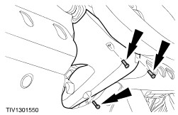
Remove the driver side instrument panel lower panel. - Remove the screw covers.
- Remove the screws.
| All Vehicles | | -
Remove the steering column lower shroud. | | | -
Remove the steering column upper shroud. | | | -
Disconnect the air bag sliding contact electrical connectors. | | | -
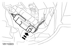
Detach the air bag sliding contact electrical connector from the steering column. - Use an electrical screwdriver to detach the electrical connector.
| | | -
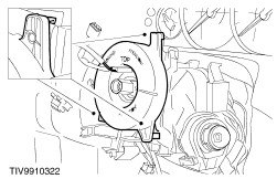
Detach the air bag sliding contact. - Release each of the three retaining tangs using an electrical screwdriver.
| | | -
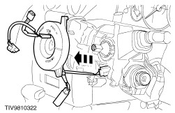
Remove the air bag sliding contact. - Feed the electrical connectors through the steering column casting.
| Installation All Vehicles | | -
WARNING:The sliding contact centralizing procedure must be carried out before installing the sliding contact. WARNING:If there is any doubt when carrying out the centralizing procedure, REPEAT the centralizing procedure. Failure to follow this warning may cause component failure and cause personal injury. Centralize the sliding contact. - Rotate the inner rotor against the outer rotor fully COUNTERCLOCKWISE until it stops.
- Rotate the inner rotor CLOCKWISE approximately 2.75 turns until the alignment markings are aligned and the locking tab locates into the slot.
| | | -
NOTE:Make sure the retaining tangs lock into position. Install the sliding contact. - Feed the electrical connectors through the steering column casting.
| | | -
Install the sliding contact electrical connector onto the steering column. - Connect the sliding contact electrical connector.
- Attach the sliding contact to electrical connector to the steering column.
| | | -
Connect the electrical connector. - Attach the electrical connectors to the steering column.
| | | -
Install the steering column upper shroud. | | | -
Install the steering column lower shroud. | Right-hand drive vehicles | | -
Install the driver side instrument panel lower panel. - Engage the four retaining clips.
| Left-hand drive vehicles | | -
Install the driver side instrument panel lower panel. - Install the bolts.
- Install the covers.
| All Vehicles |