ford Workshop Repair Guides

Ford Workshop Service and Repair Manuals

Disassembly and Assembly of Subassemblies > < Transaxle
Automatic Transmission/Transaxle - Transaxle Fiesta 1996 (08/1995-02/2002)
Disassembly

Special Tool(s)

Remover, pinion gear oil seal

205-078 (15-048)

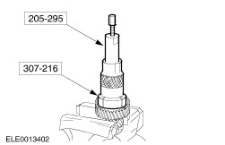
Remover, bearing (base tool)

205-295 (15-050 A)

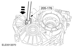
Removal drift, differential bearing cups

205-176 (15-074)

Remover, axle oil seal

303-112 (21-051)

Mounting frame for 303-435

307-200 (17-032)

Extractor, oil pump

307-203 (17-034)

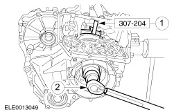
Primary unit locking tool

307-204 (17-035)

Remover, housing half (secondary unit)

307-205 (17-036)

Remover, housing half (primary unit)

307-206 (17-037)

Remover, secondary unit

307-207 (17-038)

Remover, sensor shaft

307-208 (17-039)

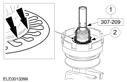
Spring washer compressor

307-209 (17-040)

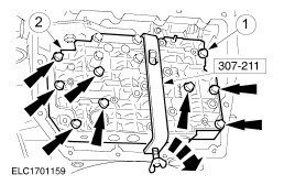
Holding clamp, control piston

307-211 (17-042 A)

Secondary unit dummy spacer

307-215 (17-046)

Collet for 205-295

307-216 (17-047)

Collet for 205-295

307-217 (17-048)

General Equipment
41 mm socket wrench
46 mm socket wrench
Internal extractor
Materials
Name
Specification
Automatic transmission fluid
WSS-M2C202-B 
Cable ties
 
Vaseline
SM-1C115-A 

Disassembly

  1. CAUTION:
    CAUTION:If abraded metal particles are identified, fit a new valve body, new oil pipes and a new oil cooler.
    CAUTION:
    CAUTION:Do not turn the transmission over in the assembly stand.
    NOTE:
    NOTE:Clean the transmission assembly to prevent dirt entering during assembly.
    NOTE:
    NOTE:Use soft jaw inserts for any vice work.
    NOTE:
    NOTE:Only paraffin should be used to clean transmission components.
    NOTE:
    NOTE:Do not allow friction plates to come into contact with cleaning agent.
    NOTE:
    NOTE:Lay out the removed parts so they can be easily inspected for damage and in a way that will facilitate re-assembly.
    NOTE:
    NOTE:If deposits are identified in the transmission fluid during repairs (abraded particles from the clutch or metallic swarf), the transmission assembly must be completely dismantled and cleaned.
    NOTE:
    NOTE:Also carefully clean the oil lines and the oil cooler. Fit new ones if they are extremely clogged.
    NOTE:
    NOTE:All clutches at which the end float is measured must be pressed together before measuring in order to force out the oil from between the plates.
    NOTE:
    NOTE:When using new clutch plates, immerse them in automatic transmission fluid for 30 minutes before fitting them.
    NOTE:
    NOTE:Lubricate all sliding components with automatic transmission fluid prior to assembly.
    NOTE:
    NOTE:Position the thrust washers and needle roller bearings with Vaseline during assembly.
    Secure the transmission to the assembly stand.

  1. Detach the oil pan downwards.

  1. NOTE:
    NOTE:Use the deposits in the oil pan to assist with fault diagnosis. Refer to the General Instructions for more information.
    Deposits in the oil pan.
    • Remove the gasket.
    • Remove the permanent magnet.
    • Turn the transmission through 90 degrees.

  1. CAUTION:
    CAUTION:Remove only where necessary (leaking or faulty).
    Remove the speedometer drive pinion.
    • Withdraw the roll pin.
    • Withdraw the sleeve with the drive gear.

  1. Detach the oil strainer and the start inhibit switch.
    1. Unscrew the bolt and remove the oil strainer.
    1. Remove the seal ring.
      CAUTION:
      CAUTION:Remove the start inhibit switch only where necessary (leaking or faulty).
    1. Remove the start inhibit switch.

  1. CAUTION:
    CAUTION:Only remove the bolts indicated in the diagram.
    Remove five screws from the valve body.

  1. Tension the control piston.
    • Attach the special tool and tighten the knurled bolt finger tight.

  1. CAUTION:
    CAUTION:Only remove the bolts indicated in the diagram.
    NOTE:
    NOTE:The manual valve can fall out of the valve body.
    Remove the valve body.
    1. Remove the bolts. Remove the valve body.
    1. Pull out the manual valve (attached below the valve body).

  1. Remove the secondary pressure adjusting sleeve.
    1. Remove the dust cap. Slacken the blanking plug one turn.
    1. Using a 4 mm Allen key, press the adjusting sleeve in against the spring pressure and hold it in position.
    • Unscrew the blanking plug.

  1. Remove the adjusting sleeve.
    • Withdraw the sleeve with the Allen key.

  1. Remove the sensor shaft.
    1. Insert the special tools.
    1. Withdraw the retaining clip.

  1. Remove the transmission gear sensor.
    1. Withdraw the sensor shaft.
    1. Remove the spring.
    1. Swivel the sensor towards the left and remove it.

  1. Detach the primary unit blanking cover.
    • Remove the O-ring.

  1. Remove the engine pitot chamber.
      NOTE:
      NOTE:Do not remove the bolt.
    1. Slacken the engine pitot tube bolt about eight turns to block the engine pitot chamber.
    1. Remove the engine pitot chamber bolts.
    • Remove the engine pitot tube bolt.

  1. Remove the engine pitot chamber.
    1. Turn the engine pitot tube anticlockwise as far as it will go.
    1. Remove the engine pitot chamber.
    • Remove the engine pitot tube.

  1. CAUTION:
    CAUTION:Only remove the bolts shown with arrows, two bolts remain in the oil pump.
    Release the oil pump.
    1. Remove the oil filler pipe.
    1. Remove the bolts.

  1. Remove the oil pump.
    1. Screw in the threaded pins.
    1. Withdraw the oil pump evenly.

  1. Remove the oil pump.
    • Remove the spring washer.
    • Remove the special tool.

  1. Check the oil pump.
    • Remove the seal ring.
      NOTE:
      NOTE:The oil pump must not be dismantled any further.
    • Determine the width of the annular groove on the oil pump. Max: 2,6 mm.

  1. Detach the secondary unit housing cover.
    • Remove the seal ring.

  1. Remove the secondary unit cover with permanent magnet.
    • Remove the viton seal ring.

  1. Unscrew the primary unit nut.
    1. Insert the special tool into the forward clutch.
    1. Unscrew the nut using a 46 mm socket.

  1. Unscrew the secondary unit nut.
    1. Turn the selector lever until the parking pawl engages.
      NOTE:
      NOTE:Secure the selector lever to prevent it from turning while the secondary unit nut is removed.
    1. Unscrew the nut using a 41 mm socket.

  1. Remove the selector shaft.
    1. Unscrew the notched disc, and detach the gearshift linkage.
    1. Detach the selector lever.
    1. Remove the retaining bolt and slide the shaft out towards the valve body/labyrinth.

  1. NOTE:
    NOTE:Turn the pitot tube anti-clockwise as far as it will go.
    Mount the special tool.

  1. Remove the housing bolts.
    1. Remove the differential auxiliary plug.
    1. Unscrew all the bolts apart from two opposite each other. Turn the transmission through 90 degrees and remove the remaining screws.

  1. Separate the housing halves evenly.

  1. CAUTION:
    CAUTION:Check the mark indicating the direction of rotation of the belt and renew it if necessary.
    Detach the transmission pitot chamber.
    1. Unscrew the bolts and remove the transmission pitot chamber.
    1. Secure the drive belt using two cable ties(opposite each other).

  1. NOTE:
    NOTE:Always attach a spacer ring and nut.
    Remove the drive belt.
    1. Attach the spacer ring with the original nut.
    1. Insert the puller into the groove in the secondary unit and secure it.
    1. Pretension the secondary unit up to the stop.
    1. Slide the drive belt onto the smaller diameter of the secondary unit.

  1. Remove the drive belt.
    • Lift the secondary unit and steel belt.
      NOTE:
      NOTE:The secondary unit must not be dismantled any further.
    • Move the secondary unit and drive belt towards the primary unit so that the drive belt can be removed from the primary unit.
    • Remove the secondary unit and drive belt together.

  1. Remove the primary unit and forward clutch.

  1. Remove the planetary gear carrier.
    • Remove the thrust washer and the adjusting shim.

  1. Remove the reverse clutch.
    1. Remove the snap-ring.
    1. Take out the plate pack.

  1. NOTE:
    NOTE:When carrying out repairs, use only new pattern clutch plates.
    Clutch plate identification.
      NOTE:
      NOTE:Soak the clutch plates in automatic transmission fluid for at least one hour before installing them.
    1. New pattern.
    1. Old pattern.

  1. Remove the reverse clutch actuating piston.
    1. Remove the snap-ring.
    1. Remove the spring washer.
    1. Remove the piston.

  1. NOTE:
    NOTE:The bearing cup slide-fits into the bearing cap.
    Remove the reduction gear bearing cap.
    1. Unhook the parking pawl spring and swing the parking pawl back.
    1. Unscrew the bolts.
    • Prise off the bearing cap.
    • Press the bearing cup out of the bearing cap.

  1. Remove the reduction gear and the differential.
    1. Reduction gear.
    1. Differential

  1. Remove the oil seals.
    1. From the input shaft.
    1. From the axle shaft.
    1. From the selector shaft (lever out with a screwdriver).

  1. Drive out the differential bearing cup.

  1. Pull out the input shaft needle roller bearing using an internal puller.

  1. NOTE:
    NOTE:Only remove the secondary unit roller bearing if it is damaged.
    Remove the secondary unit roller bearing.
    • Remove the rollers and the bearing cage.

  1. Remove the reduction gear bearing cup with the spacer.
    • Bearing cup is a sliding fit.

  1. Remove the differential bearing cup with the adjusting shim.

  1. Remove the ball bearing and the splash tube.
    1. From the primary unit.
    1. From the secondary unit
    • Drive out both bearings using a suitable drift.
    1. Undo and pull out the oil spray pipe.

  1. Remove the forward clutch.
    1. Remove the snap-ring.
    1. Take out the complete set of clutch plates.

  1. Remove the forward clutch actuating piston.
    1. Remove the snap-ring.
    1. Remove the spring washer.

  1. CAUTION:
    CAUTION:The primary unit must only be dismantled as far as described.
    Remove the forward clutch actuating piston.
    1. Remove the pressure plate and the actuating piston.
    1. Remove the seal rings.

  1. CAUTION:
    CAUTION:The secondary unit must only be dismantled as far as described.
    NOTE:
    NOTE:Only remove the secondary unit roller bearing if it is damaged.
    Pull off the secondary unit bearing inner race.
    1. Remove the snap-ring.
    1. Pull off the bearing cup.

  1. Dismantle the reduction gear.
    • Pull off the two bearings.

Disassembly and Assembly of Subassemblies > < Transaxle