| Installation Special Tool(s) | | Boot clamp tightening tool 204-169 (14-044) | Installation All vehicles | | -
NOTE:Make sure the transmission is seated securely on the transmission jack. General note. - Place the transmission on the transmission jack and position it in the correct installation position under the car.
- Renew all snap rings and self-locking nuts.
- Fix the adapter plate onto the guide sleeves on the engine.
| | | -
CAUTION:Ensure that the two guide sleeves are installed. Locate the transmission up against the engine. | | | -
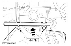
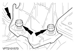
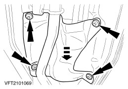
Do up the upper flange bolts. | | | -
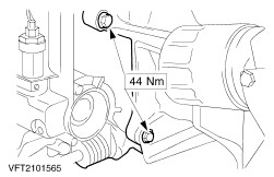
NOTE:Attach the CKP sensor cover. Do up the left-hand flange bolts. | | | -
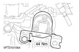
Do up the right-hand flange bolts. | | | -
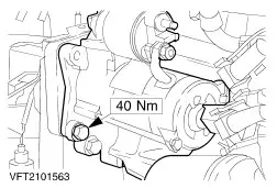
Fit the starter motor. - Attach the retaining plate.
- Starter motor
| | | -
Lower the vehicle. NOTE:Do not tighten the nuts. Raise the engine and fit the rear engine mounting. | Vehicles with a one-part intermediate shaft | | -
CAUTION:The inner joint must not be bent at more than 18 degrees; the outer joint must not be bent at more than 45 degrees. CAUTION:When installing the front driveshafts, use the locating sleeve (supplied with each new oil seal) to protect the oil seal. NOTE:Make sure the snap ring engages correctly. Install the right-hand front driveshaft with a new snap ring and the intermediate shaft in the transmission. | | | -
CAUTION:The inner joint must not be bent at more than 18 degrees; the outer joint must not be bent at more than 45 degrees. Tighten the front drive halfshaft centre bearing. | | | -
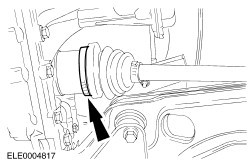
CAUTION:The inner joint must not be bent at more than 18 degrees; the outer joint must not be bent at more than 45 degrees. Install the left-hand front drive halfshaft together with tripode joint into the tripode housing. | Vehicles with a two-part intermediate shaft | | -
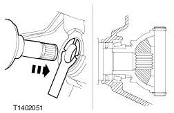
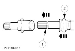
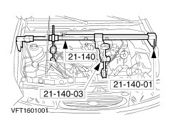
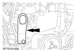
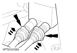
CAUTION:The inner joint must not be bent at more than 18 degrees; the outer joint must not be bent at more than 45 degrees. NOTE:The intermediate shaft extension remains in the transmission. Insert the intermediate shaft into the intermediate shaft extension (shown with the intermediate shaft extension removed). - Apply high-durability grease to the splines of the intermediate shaft and insert it into the intermediate shaft extension.
- Slide on the boot and clamping straps.
| | | -
CAUTION:The inner joint must not be bent at more than 18 degrees; the outer joint must not be bent at more than 45 degrees. Tighten the front drive halfshaft centre bearing. | | | -
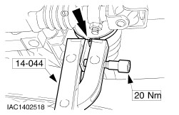
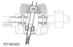
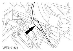
NOTE:Apply the special tool so that the clamp head is vertical to the clamping strap head. Tighten the clamping straps. | | | -
Tighten the clamping strap. | | | -
Top up transmission fluid (WSD-M2C200-C) to 5 - 10 mm below the lower edge of the fill hole. | All vehicles | | -
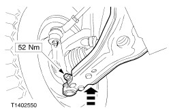
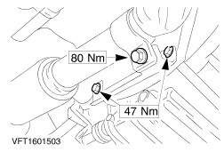
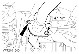
Attach the left and right suspension arms (left-hand side shown). | | | -
Attach the exhaust pipe bracket and the exhaust pipe. | | | -
Fit the engine roll restrictor. | | | -
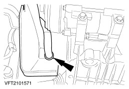
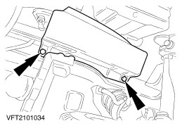
NOTE:The coolant hose must be clipped into its retaining bracket. Attach the lower drive belt cover. | | | -
Attach the lower drive belt cover. | | | -
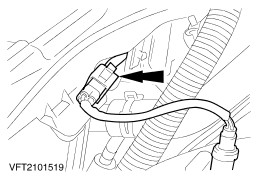
Connect the plug of the multi-function switch. | | | -
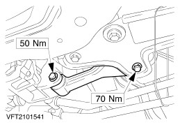
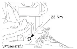
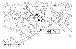
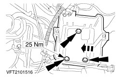
Tighten the rear engine mounting bracket. | | | -
Remove the special tools. | | | -
Detach the rear engine lifting eye. | | | -
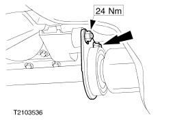
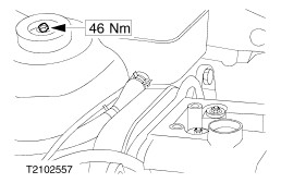
Tighten the nut on the exhaust flange. | | | -
Detach the front engine lifting eye. | | | -
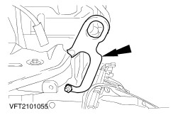
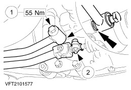
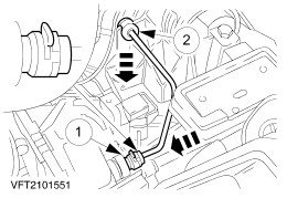
NOTE:Do not tighten the bolt on the selector shaft. Attach the selector shaft and the gearshift stabilizer to the transmission. - Selector shaft stabilizer
- Selector shaft
| | | -
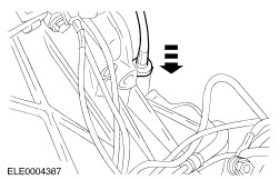
Connect the exhaust system. - Remove the boot from the flexible pipe.
| | | -
Adjust the gearshift mechanism. - Shift the transmission into fourth gear (from neutral, push the selector shaft forwards).
- Lock the gearshift mechanism in fourth gear position with the shaft of a 9 mm drill bit in the gearshift housing.
| | | -
Adjust the gearshift mechanism. | | | -
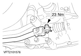
Tighten the selector shaft bolt. - Remove the twist drill bit from the selector mechanism.
| | | -
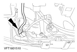
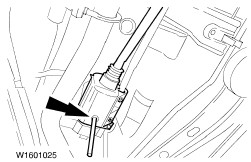
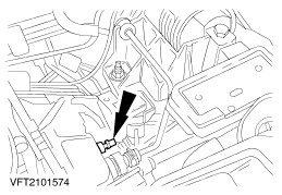
NOTE:Make sure the spring clip engages securely. Fit the hydraulic pipe of the clutch operating mechanism. - Insert the spring clip and connect the pipe to the pre-loading valve.
- Press the pipe into the guide.
| | | -
Connect the VSS sensor plug. | | | -
Attach the speedometer drive cable. | | | -
Connect the transmission ground lead. | | | -
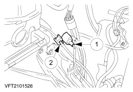
Connect the starter motor solenoid switch plug. - Starter motor solenoid switch plug.
- Clip the wiring brackets in place.
| | | -
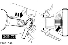
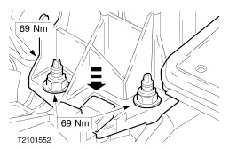
Tighten the suspension strut nuts on the right and left. - Stop it from turning with an Allen key.
- Tighten by hand with a ring spanner.
- Use a torque wrench to tighten to specified torque.
| | | -
Finishing operations. - Check the routing of cables and hoses and fix them in place with cable ties.
- Reprogram the preset radio stations.
- Check the fluid levels and correct as necessary.
- Carry out a road test to enable the PCM to gather data.
| |