| Diagnosis and Testing Refer to Wiring Diagrams Section 419-01A, for schematic and connector information. Anti-Theft Alarm/Double Locking Self-Diagnostic Mode The anti-theft alarm/double locking Self-Diagnostic Mode is designed to enable service personnel to trace faults easily. Inspection and Verification - Verify the customer concern.
- Visually inspect for obvious signs of mechanical or electrical damage.
Visual Inspection Chart | Mechanical | Electrical | | Door lock cylinder(s) | Fuse(s) | | Liftgate lock cylinder | Electrical connector(s) | | - | Wiring harness | | - | Switch(es) | | - | Remote keyless entry (RKE) receiver | | - | Anti-theft alarm horn | | - | Remote control transmitter | | - | Anti-theft alarm and double locking module | - Verify the following systems are working correctly:
- Central locking.
- Turn signals.
If a particular system(s) is not working correctly, refer to the appropriate section of the workshop manual. - If an obvious cause for an observed or reported concern is found, correct the cause (if possible) before proceeding to the next step.
- If the concern is not visually evident, verify the symptom and enter Self-Diagnostic Mode.
Self-Diagnostic Mode NOTE:The self-diagnostic mode can not be entered if the central locking system is activated. - To enter self-diagnostic mode, make sure the ignition is in the OFF position.
- Operate any door ajar switch or the hood switch 6 times within 8 seconds.
- Upon entering the self-diagnostic mode the Passive Anti-Theft System (PATS) Light Emitting Diode (LED) will illuminate continuously, the anti-theft alarm horn beeps once and the directional indicators flash once.
- Each activation of a door ajar switch or hood switch is indicated by one short horn beep.
- The activation of the ignition switch (from position 0 to II) is indicated by one short horn beep
- Each activation of a set/reset switch (located on the lock barrel of each front door) is indicated by one short horn beep, if the key is held in the lock/unlock position for a further three seconds the central locking signal (status of the lock/unlock lines) is also indicated by second short horn beep.
- If there is no activation of any alarm switch for a period of 20 seconds, the system will exit the self-diagnostic mode (indicated by one short horn beep and a single flash from the directional indicators) and the PATS LED will extinguish.
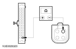
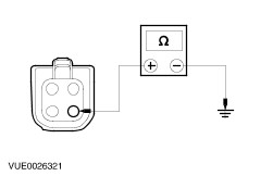
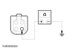
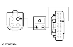
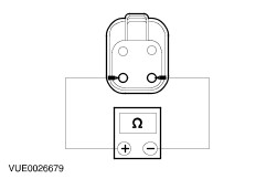
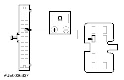
Service Test Mode Sequences Self-Diagnostic Mode | Test | Step | Result | Action | | - | Entering self-diagnostic mode | Anti-theft alarm horn beeps once and the turn indicators flash once. | If the turn signal lamps do not flash, GO to Pinpoint Test A. . | | 1 | Turn the ignition switch from position 0 to position II | Anti-theft alarm horn beeps once. | If the anti-theft alarm horn does not beep, GO to Pinpoint Test B. . | | 2 | Open each door in turn | Anti-theft alarm horn beeps once per door. | If the anti-theft alarm horn does not beep for a door, GO to Pinpoint Test C. . | | 3 | Depress the hood switch | Anti-theft alarm horn beeps once. | If the anti-theft alarm horn does not beep, GO to Pinpoint Test D. . | | 4 | Insert the key in the driver side door lock and hold it in the lock (set) position | Anti-theft alarm horn beeps twice. | If the anti-theft alarm horn does not beep, GO to Pinpoint Test E. . If the anti-theft alarm horn only beeps once, GO to Pinpoint Test F. . | | 5 | Insert the key in the driver side door lock and hold it in the unlock (reset) position | Anti-theft alarm horn beeps twice. | If the anti-theft alarm horn does not beep, GO to Pinpoint Test G. . If the anti-theft alarm horn only beeps once, GO to Pinpoint Test F. . | | 6 | Insert the key in the passenger side door lock and hold it in the lock (set) position | Anti-theft alarm horn beeps twice. | If the anti-theft alarm horn does not beep, GO to Pinpoint Test H. . If the anti-theft alarm horn only beeps once, GO to Pinpoint Test I. . | | 7 | Insert the key in the passenger side door lock and hold it in the unlock (reset) position | Anti-theft alarm horn beeps twice. | If the anti-theft alarm horn does not beep, GO to Pinpoint Test J. . If the anti-theft alarm horn only beeps once, GO to Pinpoint Test I. . | | 8 | Insert the key in the liftgate lock and operate the anti-theft alarm inhibit switch | Anti-theft alarm horn beeps once. | If the anti-theft alarm horn does not beep, GO to Pinpoint Test K. . | If the concern is still evident after the self-diagnostic mode refer to the Symptom Chart. Symptom Chart Symptom Chart | Symptom | Possible Sources | Action | | The alarm system does not arm using the remote transmitter | * Remote trasmitter. * RKE receiver. | * REFER to WDS. | | * Anti-theft alarm and double locking module. | * If the central locking is working with the remote transmitter, INSTALL a new anti-theft alarm and double locking module. TEST the system for normal operation. | Pinpoint Tests | PINPOINT TEST A : THE TURN SIGNAL LAMPS DO NOT FLASH WHEN ENTERING SELF-DIAGNOSTIC MODE | | TEST CONDITIONS | DETAILS/RESULTS/ACTIONS | | A1: CHECK THE ANTI-THEFT ALARM INDICATOR RELAY POWER SUPPLY | | | 1 Disconnect Anti-theft alarm indicator relay C19. | | | 2 Measure the voltage between the anti-theft alarm indicator relay C19, circuit 29-MB22 (OG/GN), harness side and ground. | | | Is the voltage greater than 10 volts? Yes No REPAIR circuit 29-DA2 (OG/BU). TEST the system for normal operation. | | A2: CHECK THE ANTI-THEFT ALARM INDICATOR RELAY CIRCUIT | | | 1 Disconnect Anti-theft alarm and double locking module C16b. | | | 2 Measure the resistance between the anti-theft alarm and double locking module C16b pin 9, circuit 31S-MB22 (BK/RD), harness side and anti-theft alarm indicator relay C19, circuit 31S-MB22 (BK/RD), harness side. | | | Is the resistance less than 5 ohms? Yes INSTALL a new anti-theft alarm and double locking module. TEST the system for normal operation. No REPAIR circuit 31S-MB22 (BK/RD). TEST the system for normal operation. | | PINPOINT TEST B : THE ANTI-THEFT ALARM HORN DOES NOT BEEP DURING IGNITION SWITCH ACTIVATION | | TEST CONDITIONS | DETAILS/RESULTS/ACTIONS | | B1: CHECK THE ANTI-THEFT ALARM HORN CIRCUIT FOR OPEN | | | 1 Ignition switch in position 0. | | | 2 Disconnect Anti-theft alarm and double locking module C16a. | | | 3 Ignition switch in position II. | | | 4 Measure the resistance between the anti-theft alarm and double locking module C16a, circuit 14-AA17 (VT/WH), harness side and ground. | | | Is the resistance less than 5 ohms? Yes No REPAIR circuit 14-AA17 (VT/WH). TEST the system for normal operation. | | B2: CHECK THE ANTI-THEFT ALARM AND DOUBLE LOCKING MODULE POWER SUPPLY | | | 1 Ignition switch in position 0. | | | 2 Disconnect Anti-theft alarm and double locking module C16b. | | | 3 Ignition switch in position II. | | | 4 Measure the voltage between the anti-theft alarm and double locking module C16b pin 15, circuit 74-AA17A (BU/OG), harness side and ground. | | | Is the voltage greater than 10 volts? Yes INSTALL a new anti-theft alarm and double locking module. TEST the system for normal operation. No REPAIR circuit 74-AA17A (BU/OG). TEST the system for normal operation. | | PINPOINT TEST C : THE ANTI-THEFT ALARM HORN DOES NOT BEEP DURING A DOOR AJAR SWITCH ACTIVATION | | TEST CONDITIONS | DETAILS/RESULTS/ACTIONS | | C1: CHECK THE DOOR AJAR SWITCH CIRCUIT(S) | | | 1 Disconnect Inoperative door ajar switch electrical connector. - N239 - Driver side front door. Circuit 31-MB46 (BK).
- N240 - Passenger side front door. Circuit 31-MB46 (BK).
- N237 - Driver side rear door. Circuit 31-MB48 (BK).
- N238 - Passenger side rear door. Circuit 31-MB48 (BK).
- N87 - RH side rear door (Courier). Circuit 31-MB20 (BK).
| | | 2 Connect a fused jumper wire between the inoperative door ajar switch electrical connectors pin 1, harness side and pin 2, harness side. | | | 3 Ignition switch in position II. | | | 4 Observe the instrument cluster door ajar warning indicator. | | | Does the door ajar warning indicator illuminate? Yes INSTALL a new door ajar switch. TEST the system for normal operation. No | | C2: CHECK THE INOPERATIVE DOOR AJAR SWITCH GROUND CIRCUIT | | | 1 Measure the resistance between the inoperative door ajar switch electrical connector pin 1, (BK), harness side and ground. | | | Is the resistance less than 5 ohms? Yes No REPAIR the inoperative circuit. TEST the system for normal operation. | | C3: CHECK THE INOPERATIVE DOOR AJAR SWITCH TO ANTI-THEFT ALARM AND DOUBLE LOCKING MODULE CIRCUIT FOR OPEN | | | 1 Disconnect Anti-theft alarm and double locking module C16b. | | | 2 Measure the resistance between the inoperative door ajar switch pin 2, circuit 31S-MB46 (BK/YE) (front doors), circuit 31S-MB48 (BK/OG) (rear doors), harness side and anti-theft alarm and double locking module C16b, - Pin 6, circuit 31S-MB47 (BK/BU) - RH side front door
- Pin 8, circuit 31S-MB46 (BK/YE) - LH side front door
- Pin 5, circuit 31S-MB49 (BK/OG) - Driver side rear door
- Pin 7, circuit 31S-MB48 (BK/OG) - Passenger side rear door
- Pin 24. circuit 31S-MB20 (BK/RD) - RH side rear door (Courier)
| | | Is the resistance less than 5 ohms? Yes INSTALL a new anti-theft alarm and double locking module. TEST the system for normal operation. No REPAIR the circuit. TEST the system for normal operation. | | PINPOINT TEST D : THE ANTI-THEFT ALARM HORN DOES NOT BEEP DURING THE HOOD SWITCH ACTIVATION | | TEST CONDITIONS | DETAILS/RESULTS/ACTIONS | | D1: CHECK THE HOOD SWITCH FOR CORRECT OPERATION | | | 1 Disconnect Hood switch C343. | | | 2 Measure the resistance between the hood switch C343 pin 1 and pin 2, component side, with the hood switch pressed and also released. | | | Are the resistances greater than 10,000 ohms with the hood switch pressed and less than 5 ohms with the hood switch released? Yes No INSTALL a new hood switch. TEST the system for normal operation. | | D2: CHECK THE HOOD SWITCH GROUND CIRCUIT | | | 1 Measure the resistance between the hood switch C343 pin 1, circuit 31-MB7 (BK), harness side and ground. | | | Is the resistance less than 5 ohms? Yes No REPAIR circuit 31-MB7 (BK). TEST the system for normal operation. | | D3: CHECK THE HOOD SWITCH TO ANTI-THEFT ALARM AND DOUBLE LOCKING MODULE CIRCUIT FOR OPEN | | | 1 Disconnect Anti-theft alarm and double locking module C16b. | | | 2 Measure the resistance between the hood switch C343 pin 2, circuit 31S-MB7 (BK/YE), harness side and anti-theft alarm and double locking module C16b pin 4, circuit 31S-MB7 (BK/YE), harness side. | | | Is the resistance less than 5 ohms? Yes INSTALL a new anti-theft alarm and double locking module. TEST the system for normal operation. No REPAIR circuit 31S-MB7 (BK/YE). TEST the system for normal operation. | | PINPOINT TEST E : THE ANTI-THEFT ALARM HORN DOES NOT BEEP DURING THE DRIVER SIDE DOOR LOCK (SET) SWITCH ACTIVATION | | TEST CONDITIONS | DETAILS/RESULTS/ACTIONS | | E1: CHECK THE DRIVER SIDE DOOR LOCK SWITCH GROUND CIRCUIT | | | 1 Insert the key in the driver side door lock and hold it in the unlock (reset) position. | | | Does the anti-theft alarm horn beep? Yes No | | E2: CHECK THE DRIVER SIDE DOOR LOCK SWITCH FOR OPEN | | | 1 Disconnect Driver side door lock switch C145. | | | 2 Measure the resistance between the driver side door lock switch C145 pin 1 and pin 3, component side with the switch in the lock (set) position. | | | Is the resistance less than 5 ohms? Yes No | | E3: CHECK THE DRIVER SIDE DOOR LOCK SWITCH TO ANTI-THEFT ALARM AND DOUBLE LOCKING MODULE CIRCUIT FOR OPEN | | | 1 Disconnect Anti-theft alarm and double locking module C16b. | | | 2 Measure the resistance between the anti-theft alarm and double locking module C16b pin 14, circuit 8-AA46 (WH/VT), harness side and driver side door lock switch C145 pin 1, circuit 8-AA45 (WH/RD), harness side. | | | Is the resistance less than 5 ohms? Yes INSTALL a new anti-theft alarm and double locking module. TEST the system for normal operation. No REPAIR circuit 8-AA46 (WH/VT). TEST the system for normal operation. | | E4: CHECK THE DRIVER SIDE DOOR LOCK SWITCH GROUND CIRCUIT FOR OPEN | | | 1 Disconnect Driver side door lock switch C145. | | | 2 Measure the resistance between the driver side door lock switch C145 pin 3, circuit 31-AA45 (BK), harness side and ground. | | | Is the resistance less than 5 ohms? Yes INSTALL a new driver side door lock switch. TEST the system for normal operation. If the concern persists, INSTALL a new anti-theft alarm and double locking module. No REPAIR circuit 31-AA45 (BK). TEST the system for normal operation. | | PINPOINT TEST F : THE ANTI-THEFT ALARM HORN ONLY BEEPS ONCE DURING THE DRIVER SIDE DOOR LOCK/UNLOCK (SET/RESET) SWITCH ACTIVATION | | TEST CONDITIONS | DETAILS/RESULTS/ACTIONS | | F1: CHECK THE CENTRAL LOCKING SYSTEM FOR CORRECT OPERATION | | | 1 Make sure all doors are closed. | | | 2 Check the central locking system for correct operation. | | | Does the central locking work correctly? Yes INSTALL a new anti-theft alarm and double locking module. TEST the system for normal operation. No CHECK the driver side door lock barrel, connecting rod and door lock motor. INSTALL new parts as necessary. TEST the system for normal operation. | | PINPOINT TEST G : THE ANTI-THEFT ALARM HORN DOES NOT BEEP DURING THE DRIVER SIDE DOOR UNLOCK (RESET) SWITCH ACTIVATION | | TEST CONDITIONS | DETAILS/RESULTS/ACTIONS | | G1: CHECK THE DRIVER SIDE DOOR LOCK SWITCH GROUND CIRCUIT | | | 1 Insert the key in the driver side door lock and hold it in the lock (set) position. | | | Does the anti-theft alarm horn beep? Yes No | | G2: CHECK THE DRIVER SIDE DOOR LOCK SWITCH FOR OPEN | | | 1 Disconnect Driver side door lock switch C145. | | | 2 Measure the resistance between the driver side door lock switch C145 pin 4 and pin 3, component side with the switch in the unlock (reset) position. | | | Is the resistance less than 5 ohms? Yes No | | G3: CHECK THE DRIVER SIDE DOOR LOCK SWITCH TO ANTI-THEFT ALARM AND DOUBLE LOCKING MODULE CIRCUIT FOR OPEN | | | 1 Disconnect Anti-theft alarm and double locking module C16b. | | | 2 Measure the resistance between the anti-theft alarm and double locking module C16b pin 13, circuit 10-AA46 (GY/WH), harness side and driver side door lock switch C145 pin 4, circuit 10-AA45 (GY/RD), harness side. | | | Is the resistance less than 5 ohms? Yes INSTALL a new anti-theft alarm and double locking module. TEST the system for normal operation. No REPAIR circuit 10-AA46. TEST the system for normal operation. | | G4: CHECK THE DRIVER SIDE DOOR LOCK SWITCH GROUND CIRCUIT | | | 1 Disconnect Driver side door lock switch C145. | | | 2 Measure the resistance between the driver side door lock switch C145 pin 3, circuit 31-AA45 (BK), harness side and ground. | | | Is the resistance less than 5 ohms? Yes INSTALL a new driver side door lock switch. TEST the system for normal operation. If the concern persists, INSTALL a new anti-theft alarm and double locking module. No REPAIR circuit 31-AA45 (BK). TEST the system for normal operation. | | PINPOINT TEST H : THE ANTI-THEFT ALARM HORN DOES NOT BEEP DURING THE PASSENGER SIDE DOOR LOCK (SET) SWITCH ACTIVATION | | TEST CONDITIONS | DETAILS/RESULTS/ACTIONS | | H1: CHECK THE PASSENGER SIDE DOOR LOCK SWITCH GROUND CIRCUIT | | | 1 Insert the key in the passenger side door lock and hold it in the unlock (reset) position. | | | Does the anti-theft alarm horn beep? Yes No | | H2: CHECK THE PASSENGER SIDE DOOR LOCK SWITCH FOR OPEN | | | 1 Disconnect Passenger side door lock switch C145. | | | 2 Measure the resistance between the passenger side door lock switch C138 pin 1 and pin 3, component side with the switch in the lock (set) position. | | | Is the resistance less than 5 ohms? Yes No | | H3: CHECK THE PASSENGER SIDE DOOR LOCK SWITCH TO ANTI-THEFT ALARM AND DOUBLE LOCKING MODULE CIRCUIT FOR OPEN | | | 1 Disconnect Anti-theft alarm and double locking module C16b. | | | 2 Measure the resistance between the anti-theft alarm and double locking module C16b pin 11, circuit 8-AA45 (WH/RD), harness side and passenger side door lock switch C138 pin 1, circuit 8-AA46 (WH/VT), harness side. | | | Is the resistance less than 5 ohms? Yes INSTALL a new anti-theft alarm and double locking module. TEST the system for normal operation. No REPAIR circuit 8-AA45 (WH/RD). TEST the system for normal operation. | | H4: CHECK THE PASSENGER SIDE DOOR LOCK SWITCH GROUND CIRCUIT | | | 1 Disconnect Passenger side door lock switch C145. | | | 2 Measure the resistance between the passenger side door lock switch C138 pin 3, circuit 31-AA46 (BK), harness side and ground. | | | Is the resistance less than 5 ohms? Yes INSTALL a new passenger side door lock switch. TEST the system for normal operation. If the concern persists, INSTALL a new anti-theft alarm and double locking module. No REPAIR circuit 31-AA46 (BK). TEST the system for normal operation. | | PINPOINT TEST I : THE ANTI-THEFT ALARM HORN ONLY BEEPS ONCE DURING THE PASSENGER SIDE DOOR LOCK/UNLOCK (SET/RESET) SWITCH ACTIVATION | | TEST CONDITIONS | DETAILS/RESULTS/ACTIONS | | I1: CHECK THE CENTRAL LOCKING SYSTEM FOR CORRECT OPERATION | | | 1 Make sure all doors are closed. | | | 2 Check the central locking system for correct operation. | | | Does the central locking work correctly? Yes INSTALL a new anti-theft alarm and double locking module. TEST the system for normal operation. No CHECK the passenger side door lock barrel, connecting rod and door lock motor. INSTALL new parts as necessary. TEST the system for normal operation. | | PINPOINT TEST J : THE ANTI-THEFT ALARM HORN DOES NOT BEEP DURING THE DRIVER UNLOCK (RESET) SWITCH ACTIVATION | | TEST CONDITIONS | DETAILS/RESULTS/ACTIONS | | J1: CHECK THE PASSENGER SIDE DOOR LOCK SWITCH GROUND CIRCUIT | | | 1 Insert the key in the passenger side door lock and hold it in the lock (set) position. | | | Does the anti-theft alarm horn beep? Yes No | | J2: CHECK THE PASSENGER SIDE DOOR LOCK SWITCH FOR CORRECT OPERATION | | | 1 Disconnect Passenger side door lock switch C138. | | | 2 Measure the resistance between the passenger side door lock switch C138 pin 4 circuit 10-A446 (GY/YE), and pin 3 circuit 31-A446 (BK), component side with the switch in the unlock (reset) position. | | | Is the resistance less than 5 ohms? Yes No | | J3: CHECK THE PASSENGER SIDE DOOR LOCK SWITCH TO ANTI-THEFT ALARM AND DOUBLE LOCKING MODULE CIRCUIT FOR OPEN | | | 1 Disconnect Anti-theft alarm and double locking module C16b. | | | 2 Measure the resistance between the anti-theft alarm and double locking module C16b pin 10, circuit 10-AA45 (GY/RD), harness side and passenger side door lock switch C138 pin 4, circuit 10-AA46 (GY/WH), harness side. | | | Is the resistance less than 5 ohms? Yes INSTALL a new anti-theft alarm and double locking module. TEST the system for normal operation. No REPAIR circuit 10-AA45 (GY/RD). TEST the system for normal operation. | | J4: CHECK THE PASSENGER SIDE DOOR LOCK SWITCH GROUND CIRCUIT | | | 1 Disconnect Passenger side door lock switch C145. | | | 2 Measure the resistance between the passenger side door lock switch C138 pin 3, circuit 31-AA46 (BK), harness side and ground. | | | Is the resistance less than 5 ohms? Yes INSTALL a new passenger side door lock switch. TEST the system for normal operation. If the concern persists, INSTALL a new anti-theft alarm and double locking module. No REPAIR circuit 31-AA46 (BK). TEST the system for normal operation. | | PINPOINT TEST K : THE ANTI-THEFT ALARM HORN DOES NOT BEEP DURING THE LIFTGATE INHIBIT SWITCH ACTIVATION | | TEST CONDITIONS | DETAILS/RESULTS/ACTIONS | | K1: CHECK THE LFTGATE INHIBIT SWITCH GROUND CIRCUIT | | | 1 Disconnect Liftgate inhibit switch C12. | | | 2 Measure the resistance between the liftgate inhibit switch C12 pin 7, circuit 31-AA30 (BK), harness side and ground. | | | Is the resistance less than 5 ohms? Yes No REPAIR circuit 31-AA30 (BK). TEST the system for normal operation. | | K2: CHECK THE LIFTGATE INHIBIT SWITCH FOR OPEN | | | 1 Measure the resistance between the liftgate inhibit switch pin 2 and pin 7, component side with the switch in the release position. | | | Is the resistance less than 5 ohms? Yes No INSTALL a new liftgate inhibit switch. TEST the system for normal operation. | | K3: CHECK THE LIFTGATE INHIBIT SWITCH TO ANTI-THEFT ALARM AND DOUBLE LOCKING MODULE CIRCUIT FOR OPEN | | | 1 Disconnect Anti-theft alarm and double locking module C16b. | | | 2 Measure the resistance between the anti-theft alarm and double locking module C16b pin 22, circuit 31S-AA30 (BK/YE), harness side and liftgate inhibit switch C12 pin 2, circuit 31S-AA30 (BK/YE), harness side. | | | Is the resistance less than 5 ohms? Yes INSTALL a new anti-theft alarm and double locking module. TEST the system for normal operation. No REPAIR circuit 31S-AA30 (BK/YE). TEST the system for normal operation. | |