| Diagnosis and Testing Refer to Wiring Diagrams Section 417-01, for schematic and connector information. Inspection and Verification - Verify the customer concern.
- Visually inspect for obvious signs of mechanical or electrical damage.
Visual Inspection Chart | Electrical | - Fuse(s)
- Circuit(s)
- Electrical connector(s)
- Bulb(s)
| - If an obvious cause for an observed or reported concern is found, correct the cause (if possible) before proceeding to the next step.
- If the cause is not visually evident, verify the symptom and refer to the Symptom Chart.
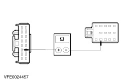
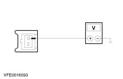
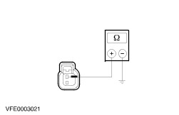
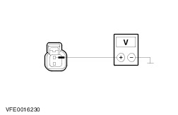
Symptom Chart Symptom Chart | Symptom | Possible Sources | Action | | Turn signal lamps are inoperative or on continuously. | * Circuit(s) * Turn signal switch * Hazard flasher switch * Instrument cluster | * | | The hazard lamps are inoperative/on continuously | * Fuse(s) * Circuit(s) * Hazard flasher switch * Anti-theft warning system/double locking module * Central junction box (CJB) | * | | One or more turn signal / hazard lamp is inoperative. | * Circuit(s) * Hazard flasher switch * Turn signal switch | * | | Turn signal lamps are working properly but there is no acoustic signal. | * Circuit(s) * Hazard flasher switch * Turn signal switch | * | Pinpoint Tests | PINPOINT TEST A : TURN SIGNAL LAMPS ARE INOPERATIVE OR ON CONTINUOUSLY | | TEST CONDITIONS | DETAILS/RESULTS/ACTIONS | | A1: DETERMINE THE FAULT CONDITION | | | 1 Ignition switch in position II. | | | 2 Actuate the RIGHT-HAND TURN SIGNAL and the LEFT-HAND TURN SIGNAL. | | | 3 Check the turn signal lamps each time for proper function. | | | Are the turn signal lamps inoperative? Yes All turn signal lamps are inoperative: GO to A2. All left-hand turn signal lamps are inoperative: GO to A9. All right-hand turn signal lamps are inoperative: GO to A12. No All left-hand turn signal lamps are on continuously: GO to A15. All right-hand turn signal lamps are on continuously: GO to A17. | | A2: CHECK THE HAZARD WARNING LAMPS | | | 1 Actuate the HAZARD WARNING. | | | Are the hazard warning lamps working properly? Yes No | | A3: CHECK THE FUSE F33 | | | 1 Ignition switch in position 0. | | | 2 CHECK Fuse F33 (CJB). | | | 3 Check fuse F33 (15A). | | | Is the fuse F33 OK? Yes No INSTALL a new fuse F33 (15 A). If the fuse blows again, LOCATE and REPAIR the short circuit by using the wiring diagrams. TEST the system for normal operation. | | A4: CHECK THE POWER SUPPLY OF THE FUSE F33 | | | 1 Connect Fuse F33 (CJB). | | | 2 Measure the voltage between fuse F33 (15 A) and ground. | | | Is battery voltage indicated? Yes No REPAIR the power supply of fuse F33, by using the wiring diagrams. TEST the system for normal operation. CHECK the CJB, if necessary INSTALL a new one. | | A5: CHECK THE POWER SUPPLY OF THE HAZARD FLASHER SWITCH | | | 1 Ignition switch in position 0. | | | 2 Disconnect Hazard flasher switch C458. | | | 3 Ignition switch in position II. | | | 4 Measure the voltage between hazard flasher switch, connector C458, pin 13, circuit 29-LG8 (OG), harness side and ground. | | | Is battery voltage indicated? Yes CHECK the hazard flasher switch. If necessary INSTALL a new one. TEST the system for normal operation No REPAIR the power supply of the hazard flasher switch, circuit 29-LG8 (OG) , by using the wiring diagrams. TEST the system for normal operation. If necessary INSTALL a new CJB. | | A6: CHECK THE FUSE F59 | | | 1 Ignition switch in position 0. | | | 2 CHECK Fuse F59 (CJB). | | | 3 Check fuse F59 (7.5A). | | | Is the fuse F59 (7.5 A) OK? Yes No INSTALL a new fuse F59 (7.5 A). If the fuse blows again, LOCATE and REPAIR the short circuit by using the wiring diagrams. TEST the system for normal operation. | | A7: CHECK THE POWER SUPPLY OF THE FUSE F59 | | | 1 Connect Fuse F59 (CJB). | | | 2 Ignition switch in position II. | | | 3 Measure the voltage between fuse F59 (7.5 A) and ground. | | | Is battery voltage indicated? Yes No REPAIR the power supply of fuse F59, by using the wiring diagrams. TEST the system for normal operation. CHECK the CJB, if necessary INSTALL a new one. | | A8: CHECK THE POWER SUPPLY OF THE TURN SIGNAL SWITCH | | | 1 Ignition switch in position 0. | | | 2 Disconnect Turn signal switch C459. | | | 3 Ignition switch in position II. | | | 4 Measure the voltage between turn signal switch, connector C459, pin 2, circuit 15-LG27 (GN/BK), harness side and ground. | | | Is battery voltage indicated? Yes CHECK the turn signal switch according to Component Testing attached to the wiring diagrams, if necessary INSTALL a new one. TEST the system for normal operation. No REPAIR the power supply of the turn signal switch, circuit 15-LG27 (GN/BK), by using the wiring diagrams. TEST the system for normal operation. | | A9: CHECK THE TURN SIGNAL SWITCH | | | 1 Ignition switch in position 0. | | | 2 Disconnect Turn signal switch C459. | | | 3 Connect a jumper wire at the turn signal switch, connector C459, between pin 2, circuit 15-LG27 (GN/BK), harness side and pin 1, circuit 15S-LG1 (GN/YE), harness side. | | | 4 Ignition switch in position II. | | | 5 Check if the left-hand turn signal lamps are working properly. | | | Are the left-hand turn signal lamps working properly? Yes CHECK the turn signal switch according to Component Testing attached to the wiring diagrams, if necessary INSTALL a new one. TEST the system for normal operation. No | | A10: CHECK THE CONTROL CIRCUIT OF THE LEFT-HAND TURN SIGNAL LAMPS | | | 1 Ignition switch in position 0. | | | 2 Connect Turn signal switch C459. | | | 3 Disconnect Hazard flasher switch C458. | | | 4 Ignition switch in position II. | | | 5 Actuate the LEFT-HAND TURN SIGNAL. | | | 6 Measure the voltage between hazard flasher switch, connector C458, pin 3, circuit , harness side and ground. | | | Is battery voltage indicated? Yes No REPAIR the open circuit 15S-LG1 (GN/YE), between turn signal switch and hazard flasher switch, by using the wiring diagrams. TEST the system for normal operation. | | A11: CHECK THE HAZARD FLASHER SWITCH | | | 1 Connect a jumper wire at the hazard flasher switch, connector C458, between pin 3, circuit 15S-LG1 (GN/YE), harness side and pin 12, circuit 49S-LG3 (BU), harness side. | | | 2 Ignition switch in position II. | | | 3 Actuate the LEFT-HAND TURN SIGNAL. | | | 4 Check if the left-hand turn signal lamps are on continuously. | | | Are the left-hand turn signal lamps on continuously? Yes CHECK the hazard flasher switch. If necessary INSTALL a new one. TEST the system for normal operation. No REPAIR the open circuit 49S-LG3 (BU) between hazard flasher switch and splice S3, by using the wiring diagrams. TEST the system for normal operation. | | A12: CHECK THE TURN SIGNAL SWITCH | | | 1 Ignition switch in position 0. | | | 2 Disconnect Turn signal switch C459. | | | 3 Connect a jumper wire at the turn signal switch, connector C459, between pin 2, circuit 15-LG27 (GN/BK), harness side and pin 3, circuit 15S-LG2 (GN/BU), harness side. | | | 4 Ignition switch in position II. | | | 5 Check if the right-hand turn signal lamps are working properly. | | | Are the right-hand turn signal lamps working properly? Yes CHECK the turn signal switch according to Component Testing attached to the wiring diagrams, if necessary INSTALL a new one. TEST the system for normal operation. No | | A13: CHECK THE CONTROL CIRCUIT OF THE RIGHT-HAND TURN SIGNAL LAMPS | | | 1 Ignition switch in position 0. | | | 2 Connect Turn signal switch C459. | | | 3 Disconnect Hazard flasher switch C458. | | | 4 Ignition switch in position II. | | | 5 Actuate the RIGHT–HAND TURN SIGNAL. | | | 6 Measure the voltage between hazard flasher switch, connector C458, pin 6, circuit , harness side and ground. | | | Is battery voltage indicated? Yes No REPAIR the open circuit 15S-LG2 (GN/BU) between turn signal switch and hazard flasher switch, by using the wiring diagrams. TEST the system for normal operation. | | A14: CHECK THE HAZARD FLASHER SWITCH | | | 1 Ignition switch in position 0. | | | 2 Connect a jumper wire at the hazard flasher switch, connector C458, between pin 6, circuit 15S-LG2 (GN/BU), harness side and pin 14, circuit 49S-LG4 (BU/RD), harness side. | | | 3 Ignition switch in position II. | | | 4 Actuate the RIGHT-HAND TURN SIGNAL. | | | 5 Check if the right-hand turn signal lamps are on continuously. | | | Are the right-hand turn signal lamps on continuously? Yes CHECK the hazard flasher switch. If necessary INSTALL a new one. TEST the system for normal operation. No REPAIR the open circuit 49S-LG4 (BU/RD) between hazard flasher switch and splice S4, by using the wiring diagrams. TEST the system for normal operation. | | A15: CHECK THE HAZARD FLASHER SWITCH | | | 1 Ignition switch in position 0. | | | 2 Disconnect Hazard flasher switch C458. | | | 3 Ignition switch in position II. | | | 4 Check if the left-hand turn signal lamps are on continuously. | | | Are all left-hand turn signal lamps on continuously? Yes No Check the hazard flasher switch. If necessary INSTALL a new one. TEST the system for normal operation. | | A16: CHECK THE INSTRUMENT CLUSTER | | | 1 Ignition switch in position 0. | | | 2 Disconnect Instrument cluster C809. | | | 3 Ignition switch in position II. | | | 4 Check if the left-hand turn signal lamps are on continuously. | | | Are all left-hand turn signal lamps on continuously? Yes REPAIR the short to power, circuits connected with the splice S3, by using the wiring diagrams. TEST the system for normal operation. No CHECK the instrument cluster. If necessary INSTALL a new one. TEST the system for normal operation. | | A17: CHECK THE HAZARD FLASHER SWITCH | | | 1 Ignition switch in position 0. | | | 2 Disconnect Hazard flasher switch C458. | | | 3 Ignition switch in position II. | | | 4 Check if the right-hand turn signal lamps are on continuously. | | | Are all right-hand turn signal lamps on continuously? Yes No Check the hazard flasher switch. If necessary INSTALL a new one. TEST the system for normal operation. | | A18: CHECK THE INSTRUMENT CLUSTER | | | 1 Ignition switch in position 0. | | | 2 Disconnect Instrument cluster C809. | | | 3 Ignition switch in position II. | | | 4 Check if the right-hand turn signal lamps are on continuously. | | | Are all right-hand turn signal lamps on continuously? Yes REPAIR the short to power, circuits connected with the splice S4, by using the wiring diagrams. TEST the system for normal operation. No CHECK the instrument cluster. If necessary INSTALL a new one. TEST the system for normal operation. | | PINPOINT TEST B : THE HAZARD LAMPS ARE INOPERATIVE/ON CONTINUOUSLY | | TEST CONDITIONS | DETAILS/RESULTS/ACTIONS | | B1: DETERMINE THE FAULT CONDITION | | | 1 Activate the hazard flasher switch. | | | 2 Check if the hazard warning lamps are inoperative. | | | Are the hazard warning lamps inoperative? Yes No The hazard warning lamps are inoperative if the anti theft is activated: GO to B3. The hazard warning lamps are on continuously: CHECK the hazard flasher switch. If necessary INSTALL a new one. TEST the system for normal operation. The hazard warning lamps are flashing continuously, without anti theft: CHECK the hazard flasher switch. If necessary INSTALL a new one. TEST the system for normal operation. The hazard warning lamps are flashing continuously, with anti theft: GO to B3. | | B2: CHECK THE GROUND SUPPLY OF THE HAZARD FLASHER SWITCH | | | 1 Ignition switch in position 0. | | | 2 Disconnect Hazard flasher switch C458. | | | 3 Measure the resistance between the hazard flasher switch, connector C458, pin 10, circuit 91-LG8 (BK/OG), harness side and ground. | | | Is the resistance less than 2 ohms? Yes CHECK the hazard flasher switch. If necessary INSTALL a new one. TEST the system for normal operation. No REPAIR the open circuit 91-LG8 (BK/OG), between hazard flasher switch and splice S12 by using the wiring diagrams. TEST the system for normal operation. | | B3: CHECK THE CONTROL CIRCUIT FROM THE ANTI THEFT MODULE | | | 1 Ignition switch in position 0. | | | 2 Disconnect Anti-theft/ central locking module C452. | | | 3 Disconnect Hazard flasher switch C458. | | | 4 Measure the resistance between the anti-theft/ central locking module, connector C452, pin 6, circuit 31S-LG8 (BK/OG), harness side and hazard flasher switch, connector C458, pin 5, circuit 31S-LG8 (BK/OG), harness side. | | | Is the resistance less than 2 ohms? Yes No REPAIR the open circuit 31S-LG8 (BK/OG) between anti-theft/ central locking module and hazard flasher switch by using the wiring diagrams. TEST the system for normal operation. | | PINPOINT TEST C : ONE OR MORE TURN SIGNAL / HAZARD LAMP IS INOPERATIVE. | | TEST CONDITIONS | DETAILS/RESULTS/ACTIONS | | C1: DETERMINE THE INOPERATIVE TURN SIGNAL LAMP | | | 1 Actuate the hazard flasher switch. | | | 2 Determine the inoperative lamp. | | | Is one of the left-hand turn signal lamps inoperative? Yes The side turn signal lamp, left-hand side is inoperative: GO to C2. The turn signal lamp, left-hand side, front is inoperative: GO to C4. The turn signal lamp, left-hand side, rear is inoperative, only 3/5 door models: GO to C6. The turn signal lamp, left-hand side, rear is inoperative, only 4 door and wagon models: GO to C8. The front and side turn signal lamp, left-hand side are inoperative: GO to C18. No The side turn signal lamp, right-hand side, is inoperative: GO to C10. The turn signal lamp, right-hand side, front is inoperative: GO to C12. The turn signal lamp, right-hand side, rear is inoperative, only 3/5 door models: GO to C14. The turn signal lamp, left-hand side, rear is inoperative, only 4 door and wagon models: GO to C16. | | C2: CHECK THE POWER SUPPLY OF THE SIDE TURN SIGNAL LAMP, LEFT-HAND SIDE | | | 1 Disconnect Side turn signal lamp, left-hand side C753. | | | 2 Actuate the HAZARD WARNING. | | | 3 Measure the voltage between the side turn signal lamp, left-hand side, connector C753, pin 2, circuit 49S-LG13 (BU/RD), harness side and ground. | | | Is alternating battery voltage indicated? Yes No REPAIR the open circuit 49S-LG13 (BU/RD) between splice S104 and side turn signal lamp, left-hand side, by using the wiring diagrams. TEST the system for normal operation. | | C3: CHECK THE GROUND SUPPLY OF THE SIDE TURN SIGNAL LAMP, LEFT-HAND SIDE | | | 1 Measure the resistance between the side turn signal lamp, left-hand side, connector C753, pin 1, circuit 31-LG13 (BK), harness side and ground. | | | Is the resistance less than 2 ohms? Yes CHECK the side turn signal lamp, left-hand side. If necessary INSTALL a new one. TEST the system for normal operation. No REPAIR the open circuit 31-LG13 (BK) between side turn signal lamp, left-hand side, and splice S121, by using the wiring diagrams. TEST the system for normal operation. | | C4: CHECK THE POWER SUPPLY OF THE TURN SIGNAL LAMP, LEFT-HAND SIDE, FRONT | | | 1 Disconnect Turn signal lamp, left-hand side, front C713. | | | 2 Actuate the HAZARD WARNING. | | | 3 Measure the voltage between the turn signal lamp, left-hand side, front, connector C713, pin 2, circuit 49S-LG11 (BU/OG), harness side and ground. | | | Is alternating battery voltage indicated? Yes No REPAIR the open circuit 49S-LG11 (BU/OG) between splice S104 and turn signal lamp, left-hand side, front, by using the wiring diagrams. TEST the system for normal operation. | | C5: CHECK THE GROUND SUPPLY OF THE TURN SIGNAL LAMP, LEFT-HAND SIDE, FRONT | | | 1 Measure the resistance between the turn signal lamp, left-hand side, front, connector C713, pin 1, circuit 31-LG11 (BK), harness side and ground. | | | Is the resistance less than 2 ohms? Yes CHECK the turn signal lamp, left-hand side. If necessary INSTALL a new one. TEST the system for normal operation. No REPAIR the open circuit 31-LG11 (BK) between turn signal lamp, left-hand side, front and splice S121, by using the wiring diagrams. TEST the system for normal operation. | | C6: CHECK THE POWER SUPPLY OF THE TURN SIGNAL LAMP, LEFT-HAND SIDE REAR | | | 1 Ignition switch in position 0. | | | 2 Disconnect Turn signal lamp, left-hand side, rear C461. | | | 3 Ignition switch in position II. | | | 4 Actuate the HAZARD WARNING. | | | 5 Measure the voltage between the turn signal lamp, left-hand side, rear, connector C461, pin 1, circuit 49S-LG12 (BU), harness side and ground. | | | Is alternating battery voltage indicated? Yes No REPAIR the open circuit(s) between splice S3 and turn signal lamp, left-hand side, rear, by using the wiring diagrams. TEST the system for normal operation. | | C7: CHECK THE GROUND SUPPLY OF THE TURN SIGNAL LAMP, LEFT-HAND SIDE, REAR | | | 1 Measure the resistance between the turn signal lamp, left-hand side, rear, connector C461, pin 2, circuit 31-LG12 (BK), harness side and ground. | | | Is the resistance less than 2 ohms? Yes CHECK the turn signal lamp, left-hand side, rear. If necessary INSTALL a new one. TEST the system for normal operation. No REPAIR the open circuit(s) between turn signal lamp, left-hand side, rear and splice S184, by using the wiring diagrams. TEST the system for normal operation. | | C8: CHECK THE POWER SUPPLY OF THE LAMP ASSEMBLY, LEFT-HAND SIDE REAR | | | 1 Disconnect Lamp assembly, left-hand side, rear C476 (4-door only) / C474 (wagon only). | | | 2 Actuate the HAZARD WARNING. | | | 3 Measure the voltage between the lamp assembly, left-hand side, rear: - 4-door only: connector C476, pin 3, circuit 49S-LG12 (BU), harness side and ground.
- Wagon only: connector C474, pin 5, circuit 49S-LG12 (BU), harness side and ground.
| | | Is alternating battery voltage indicated? Yes No REPAIR the open circuit(s) between splice S3 and lamp assembly, left-hand side, rear, by using the wiring diagrams. TEST the system for normal operation | | C9: CHECK THE GROUND SUPPLY OF THE LAMP ASSEMBLY, LEFT-HAND SIDE REAR | | | 1 Measure the resistance between the lamp assembly, left-hand side, rear: - 4-door only: connector C476, pin 6, circuit 31-LF23 (BK), harness side and ground.
- Wagon only: connector C474, pin 6, circuit 31-LF23A (BK), harness side and ground.
| | | Is the resistance less than 2 ohms? Yes CHECK the turn signal lamp, left-hand side, rear. If necessary INSTALL a new one. TEST the system for normal operation. No REPAIR the open circuit(s) between turn signal lamp, left-hand side, rear and ground, by using the wiring diagrams. TEST the system for normal operation. | | C10: CHECK THE POWER SUPPLY OF THE SIDE TURN SIGNAL LAMP, RIGHT-HAND SIDE, FRONT | | | 1 Disconnect Side turn signal lamp, right-hand side C754. | | | 2 Actuate the HAZARD WARNING. | | | 3 Measure the voltage between the side turn signal lamp, right-hand side, front, connector C754, pin 2, circuit 49S-LG20 (BU/WH), harness side and ground. | | | Is alternating battery voltage indicated? Yes No REPAIR the open circuit(s) between splice S4 and side turn signal lamp, right-hand side, front, by using the wiring diagrams. TEST the system for normal operation. | | C11: CHECK THE GROUND SUPPLY OF THE SIDE TURN SIGNAL LAMP, RIGHT-HAND SIDE | | | 1 Measure the resistance between the side turn signal lamp, right-hand side, connector C754, pin 1, circuit 31-LG20 (BK), harness side and ground. | | | Is the resistance less than 2 ohms? Yes CHECK the side turn signal lamp, right-hand side. If necessary INSTALL a new one. TEST the system for normal operation. No REPAIR the open circuit 31-LG20 (BK) between side turn signal lamp, right-hand side, front and splice S52, by using the wiring diagrams. TEST the system for normal operation. | | C12: CHECK THE POWER SUPPLY OF THE TURN SIGNAL LAMP, RIGHT-HAND SIDE, FRONT | | | 1 Disconnect Turn signal lamp, right-hand side, front C714. | | | 2 Actuate the HAZARD WARNING. | | | 3 Measure the voltage between the turn signal lamp, right-hand side, front, connector C714, pin 2, circuit 49S-LG18 (BU), harness side and ground. | | | Is alternating battery voltage indicated? Yes No REPAIR the open circuit 49S-LG18 (BU) between splice S4 and turn signal lamp, right-hand side, front, by using the wiring diagrams. TEST the system for normal operation. | | C13: CHECK THE GROUND SUPPLY OF THE TURN SIGNAL LAMP, RIGHT-HAND SIDE, FRONT | | | 1 Measure the resistance between the turn signal lamp, right-hand side, front, connector C714, pin 1, circuit 31-LG18 (BK), harness side and ground. | | | Is the resistance less than 2 ohms? Yes CHECK the turn signal lamp, right-hand side. If necessary INSTALL a new one. TEST the system for normal operation. No REPAIR the open circuit 31-LG18 (BK) between turn signal lamp, right-hand side, front and splice S109, by using the wiring diagrams. TEST the system for normal operation. | | C14: CHECK THE POWER SUPPLY OF THE TURN SIGNAL LAMP, RIGHT-HAND SIDE REAR | | | 1 Disconnect Turn signal lamp, right-hand side, rear C462. | | | 2 Actuate the HAZARD WARNING. | | | 3 Measure the voltage between the turn signal lamp, right-hand side, rear, connector C462, pin 1, circuit 49S-LG19 (BU/RD), harness side and ground. | | | Is alternating battery voltage indicated? Yes No REPAIR the open circuit 49S-LG19 (BU/RD) between splice S4 and turn signal lamp, right-hand side, rear, by using the wiring diagrams. TEST the system for normal operation. | | C15: CHECK THE GROUND SUPPLY OF THE TURN SIGNAL LAMP, RIGHT-HAND SIDE, REAR | | | 1 Measure the resistance between the turn signal lamp, right-hand side, rear, connector C462, pin 2, circuit 31-LG19 (BK), harness side and ground. | | | Is the resistance less than 2 ohms? Yes CHECK the turn signal lamp, right-hand side, rear. If necessary INSTALL a new one. TEST the system for normal operation. No REPAIR the open circuit(s) between turn signal lamp, right-hand side, rear and ground, by using the wiring diagrams. TEST the system for normal operation. | | C16: CHECK THE POWER SUPPLY OF THE LAMP ASSEMBLY, RIGHT-HAND SIDE REAR | | | 1 Disconnect Lamp assembly, right-hand side, rear C477 (4-door only) / C477 (wagon only). | | | 2 Actuate the HAZARD WARNING. | | | 3 Measure the voltage between the lamp assembly, right-hand side, rear: - 4-door only: connector C477, pin 1, circuit 49S-LG19 (BU/RD), harness side and ground.
- Wagon only: connector C475, pin 5, circuit 49S-LG19 (BU/RD), harness side and ground.
| | | Is alternating battery voltage indicated? Yes No REPAIR the open circuit 49S-LG19 (BU/RD) between splice S4 and lamp assembly, right-hand side, rear, by using the wiring diagrams. TEST the system for normal operation | | C17: CHECK THE GROUND SUPPLY OF THE LAMP ASSEMBLY, RIGHT-HAND SIDE REAR | | | 1 Measure the resistance between the lamp assembly, right-hand side, rear: - 4-door only: connector C477, pin 4, circuit 31-LF24 (BK), harness side and ground.
- Wagon only: connector C475, pin 6, circuit 31-LF24A (BK), harness side and ground.
| | | Is the resistance less than 2 ohms? Yes CHECK the turn signal lamp, right-hand side, rear. If necessary INSTALL a new one. TEST the system for normal operation. No REPAIR the open circuit 31-LF24 (A) (BK) between turn signal lamp, right-hand side, rear and ground, by using the wiring diagrams. TEST the system for normal operation. | | C18: CHECK THE POWER SUPPLY OF THE LEFT-HAND SIDE TURN SIGNAL LAMP FRONT | | | 1 Disconnect Left-hand turn signal lamp front C713. | | | 2 Actuate the LEFT-HAND TURN SIGNAL. | | | 3 Measure the voltage between the left-hand turn signal lamp, front C713, pin 2, circuit 49S-LG11 (BU/OG), harness side and ground. | | | Is an alternating voltage indicated? Yes REPAIR the open circuit 31–LG11 (BK) between splice S121 and ground, by using the wiring diagrams. TEST the system for normal operation. No REPAIR the power supply circuit, 49S-LG11 (BU/OG) between the left-hand turn signal lamp front and splice S104, by using the wiring diagrams. TEST the system for normal operation. | | PINPOINT TEST D : TURN SIGNAL LAMPS ARE WORKING PROPERLY BUT THERE IS NO ACOUSTIC SIGNAL | | TEST CONDITIONS | DETAILS/RESULTS/ACTIONS | | D1: CHECK THE GROUND SUPPLY OF THE TURN SIGNAL SWITCH | | | 1 Ignition switch in position 0. | | | 2 Disconnect Turn signal switch C459. | | | 3 Measure the resistance between turn signal switch, connector C459, pin 5, circuit 91-LG43 (BK/WH), harness side and ground. | | | Is the resistance less than 2 ohms? Yes No REPAIR the open circuit 91-LG43 (BK/WH) between the turn signal hazard switch and splice S12, by using the wiring diagrams. If necessary INSTALL a new turn signal switch. TEST the system for normal operation. | | D2: CHECK THE TURN SIGNAL SWITCH | | | 1 Actuate the HAZARD WARNING. | | | 2 Measure the voltage between turn signal switch, connector C459, pin 4, circuit 29S-LG43 (OG/WH), harness side and ground. | | | Is alternating battery voltage indicated? Yes CHECK the turn signal switch according to Component Testing attached to the wiring diagrams, if necessary INSTALL a new one. TEST the system for normal operation. No | | D3: CHECK THE BUZZER CONTROL CIRCUIT FROM THE HAZARD FLASHER SWITCH | | | 1 Disconnect Hazard flasher switch C458. | | | 2 Measure the resistance between turn signal switch, connector C459, pin 4, circuit 29S-LG43 (OG/WH), harness side and hazard flasher switch, connector C458, pin 8, circuit 29S-LG43 (OG/WH), harness side. | | | Is the resistance less than 2 ohms? Yes CHECK the hazard flasher switch. If necessary INSTALL a new one. TEST the system for normal operation. No REPAIR the open circuit 29S-LG43 (OG/WH) between turn signal switch and hazard flasher switch, by using the wiring diagrams. TEST the system for normal operation. | |