| Disassembly and Assembly Special Tool(s) | | Boot clamp tightening tool 204-169 (14-044) | General Equipment Snap-ring pliers Clamping straps Materials Name Specification High-durability grease WSD-M1C230-A Disassembly | | -
NOTE:Use protective covers. Disconnect the front drive halfshaft at the transmission end. - Clamp the front drive halfshaft in a clamp.
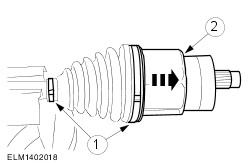
- Separate and discard the clamping straps. Push back the boot.
- Separate the tripode joint.
| | | -
Remove the tripode star and the boot. | | | -
Detach the drive halfshaft joint gaiter. - Loosen the clamping straps from the boot.
- Pull off the boot.
- Remove the grease from inside the joint.
| | | -
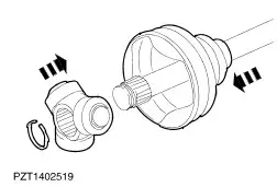
Detach the front drive halfshaft from the halfshaft joint. - Pull the front drive halfshaft from the halfshaft joint.
- Remove the circlip from the halfshaft joint.
| | | -
Detach the tripode cage and tripode star from the tripode shell. - Turn the tripode cage together with the tripode star.
- Pull the tripode cage with the tripode star out of the tripode shell.
| | | -
Remove the balls from the tripode cage. | | | -
NOTE:Make sure that the tripode housing, cage, balls and star are free of grease and oil. Check all running surfaces for wear. | Assembly | | -
NOTE:Renew all snap-rings and clamping straps. NOTE:Chamfer points towards the front drive halfshaft. Install the tripode star. - Slide the boot onto the front drive halfshaft.
- Push the tripode star onto the front drive halfshaft.
| | | -
Make a clamp head for Special Tool 14-044. - Material: aluminium or steel plate
| | | -
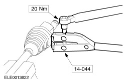
NOTE:Tighten 0,8 mm thick clamping straps to 12 Nm and 1.1 mm thick clamping straps to 20 Nm. Insert the clamping strap in the groove of the boot and tighten with the special tool. | | | -
Install the constant velocity joint at the transmission end. - Slide a small screwdriver under the boot seat to allow the air to escape.
- Slide the tripode joint inwards as far as the stop, then pull it out 20 mm.
| | | -
NOTE:Tighten 0,8 mm thick clamping straps to 12 Nm and 1,1 mm thick clamping straps to 20 Nm. Insert the clamping strap in the groove of the boot and tighten with the special tool. | | | -
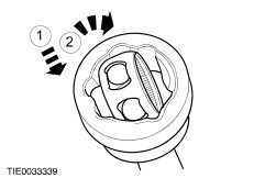
Install the balls in the tripode cage. | | | -
Install the tripode cage with tripode star in the tripode shell. - Slide the tripode cage with tripode star into the tripode shell.
- Turn the tripode cage together with the tripode star.
| | | -
NOTE:Make sure the snap-ring snaps securely into place. Fit the front drive halfshaft into the halfshaft joint. - Slide on the boot with the inner clamping strap.
- Insert a new circlip into the drive halfshaft joint groove.
- Insert the front drive halfshaft into the drive halfshaft joint until the snap-ring engages.
| | | -
- Fill level for vehicles with Endura-DE diesel engines: 40 g each side.
- Fill level for all other vehicles: 30 g each side.
- Apply the special tool so that the clamp head is vertically on the clamping strap head.
| | |