Ford Workshop Service and Repair Manuals
HOME
FEATURES
MENU
INDEX
ABOUT US
Disassembly and Assembly >
< Front Halfshaft RH
Puma 1998 (06.1997-12.2001)
Mechanical Repairs
2 Chassis
205 Driveline / 205-04 Front Drive Halfshafts
Description and Operation
Diagnosis and Testing
Removal and Installation
Outer Constant Velocity (CV) Joint
Front Drive Halfshafts - Outer Constant Velocity (CV) Joint
Puma 1998 (06/1997-12/2001)
Removal and Installation
Special Tool(s)
Driveshaft installer
14-041
Remover, front axle driveshaft
16-089
General Equipment
Two-legged puller
32 mm socket wrench
Circlip pliers
Materials
Name
Specification
High-durability grease
WSD-M1C230-A
Clamping straps
Removal
NOTE:
Use an Allen key to stop the piston rod from turning.
Undo the suspension strut nut five turns.
Undo the driveshaft stub nut and wheel nuts.
Wheel nuts
Destake the axle driveshaft stub nut and remove it with a
32 mm socket wrench
.
Raise the vehicle. For additional information, refer to Section
100-02 Jacking and Lifting
.
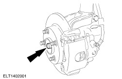
Detach the lower suspension arm from the spindle carrier (left-hand side shown).
Remove the wheel.
Undo the clamping straps and push back the gaiter of the constant velocity joint.
Remove the grease from inside the joint.
CAUTION:
The inner joint must not be bent at more than 18° and the outer joint must not be bent at more than 45°.
Remove the front wheel driveshaft from the constant velocity joint.
Open the circlip with the circlip pliers and hold it open.
Pull the constant velocity joint off the front wheel driveshaft.
Tie up the front wheel driveshaft.
Unscrew the driveshaft stub nut and remove the washer.
Pull the driveshaft stub out of the wheel hub using a
proprietary puller
.
Installation
General note.
Renew all self-locking nuts, circlips and clamping straps.
Draw the driveshaft stub into the wheel hub.
Insert the washer and screw on the driveshaft stub nut.
CAUTION:
The inner joint must not be bent at more than 18° and the outer joint must not be bent at more than 45°.
NOTE:
Ensure that the snap-ring engages securely.
Fit the front wheel driveshaft in the constant velocity joint.
Guide the front wheel driveshaft into the constant velocity joint until the circlip snaps into place.
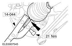
Fabricate a hold-down attachment for Special Tool 14-044.
Material: aluminium or flat rolled steel
NOTE:
Tension the gaiter clamping straps to 21 Nm.
Pack the constant velocity joint with
high-durability grease
.
Fill capacity: 80 g
Slide on the gaiter.
Fit the hold-down attachment to the special tool.
Locate the special tool in position so that the hold-down attachment bears on the gaiter clamping strap.
Attach the lower suspension arm and spindle carrier (left-hand side shown).
Fit the front wheel.
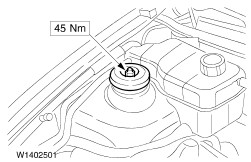
NOTE:
Use a 32 mm socket wrench.
Tighten the front wheel nuts and the driveshaft stub nut.
Lower the vehicle.
Stake the driveshaft stub nut to secure it.
Tighten the wheel nuts.
NOTE:
Use an Allen key to stop the piston rod from turning.
Tighten the suspension strut nut.
Standard finishing operations.
Road test the vehicle.
Mechanical Repairs
2 Chassis
205 Driveline / 205-04 Front Drive Halfshafts
Description and Operation
Diagnosis and Testing
Removal and Installation
Outer Constant Velocity (CV) Joint
Disassembly and Assembly >
< Front Halfshaft RH