| Diagnosis and Testing Principles of Operation The electronic speed control is restricted to vehicles with no accelerator cable. This type of speed control uses the powertrain control module (PCM), engine and transmission inputs and outputs to monitor, adjust and maintain the required vehicle speed. The PCM receives speed control commands from the steering wheel mounted speed control switches. Vehicle speed is monitored from the vehicle speed sensor (VSS) input to the instrument cluster speedometer. The speed control system will not be enabled until the vehicles indicated road speed is 42 km/h (26.3 mph) or above. At this speed, the operation of the speed control ON switch will put the speed control system into standby mode. The instrument cluster speed control indicator lamp will not be illuminated. Standby mode will be maintained until the speed control OFF switch has been operated or the ignition key has been turned to position 0. Standby mode will be maintained if the vehicle indicated speed decreases below 42 km/h (26.3 mph). Speed control cruise function is disabled until the following criteria is met: - The vehicle indicated speed is above 42 km/h (26.3 mph)
- Third gear or above must been selected
- The speed control + switch is pressed
As long as these criteria are met, the instrument cluster speed control indicator lamp will illuminate, indicating the vehicle is under speed control. To prevent the vehicle engine working against the vehicle braking system, the brake pedal position (BPP) switch is used to monitor brake pedal movement. If the BPP switch is actuated, the speed control will disengage and normal engine operation will resume. To prevent uncontrolled engine acceleration with no transmission load, the clutch pedal position (CPP) switch is used to monitor clutch pedal movement. If the CPP switch is actuated, the speed control will disengage. Inspection and Verification - Verify the customer concern.
- Visually inspect for obvious signs of mechanical or electrical damage.
Visual Inspection Chart | Mechanical | Electrical | | | - Fuse(s)
- Wiring harness
- Electrical connector(s)
- Clockspring
- Speed control switch
- BPP switch
- CPP switch
- PCM
- Central junction box (CJB)
| - If an obvious cause for an observed or reported concern is found, correct the cause (if possible) before proceeding to the next step.
- If the cause is not visually evident verify the symptom and refer to the Symptom Chart.
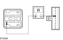
Symptom Chart | Symptom | Possible Sources | Action | | The speed control is inoperative | * Fuse(s). * Circuit(s). * Speed control switch. * BPP switch. * CPP switch. * CJB * PCM. | * | | The speed control does not disengage when the brakes are applied. | * Circuit(s). * BPP switch. * CJB | * | | The speed control does not disengage when the clutch is applied. | * Circuit(s). * CPP switch. * CJB | * | | The speed control switch does not operate correctly | * Speed control switch. | * CARRY OUT the speed control switch component test in this section. | Pinpoint Test NOTE:Use a digital multimeter for all electrical measurements. | PINPOINT TEST A : THE SPEED CONTROL IS INOPERATIVE | | TEST CONDITIONS | DETAILS/RESULTS/ACTIONS | | A1: CHECK CIRCUIT CBB18 (GY/OG) FOR POWER | | | 1 Ignition switch in position II. | | | 2 Disconnect CJB CBP02F. | | | 3 Measure the voltage between the CJB CBP02F pin 1, circuit CBB18 (GY/OG), harness side and ground. | | | Is the voltage greater than 10 volts? Yes No REPAIR the circuit. | | A2: CHECK CIRCUIT ZA233 (OG) FOR OPEN CIRCUIT | | | 1 Ignition switch in position 0. | | | 2 Remove the driver air bag.
REFER to: Driver Air Bag Module (501-20B Supplemental Restraint System, Removal and Installation).
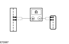
| | | 3 Disconnect Clockspring CR115A. | | | 4 Measure the resistance between the CJB CBP02F pin 26, circuit ZA233 (OG), harness side and the clockspring CR115A pin 5, circuit ZA233 (OG), harness side. | | | Is the resistance less than 1 ohm? Yes No REPAIR the circuit as necessary. TEST the system for normal operation. | | A3: CHECK CIRCUIT ZA232 (OG/VT) FOR OPEN CIRCUIT | | | 1 Measure the resistance between the CJB CBP02F pin 40, circuit ZA232 (OG/VT), harness side and the clockspring CR115A pin 4, circuit ZA232 (OG/VT), harness side. | | | Is the resistance less than 1 ohm? Yes No REPAIR the circuit. TEST the system for normal operation. | | A4: CHECK THE CLOCKSPRING FOR OPEN CIRCUIT | | | 1 Disconnect Clockspring CR115B. | | | 2 Measure the resistance between: - the clockspring CR115A pin 4, component side and the clockspring CR115B pin 2, component side.
- the clockspring CR115A pin 5, component side and the clockspring CR115B pin 3, component side.
| | | Are the resistances less than 1 ohm? Yes INSTALL a new speed control switch. TEST the system for normal operation. If the concern is still apparent, REFER to the WDS to diagnose the high speed controller area network (CAN) bus. No INSTALL a new clockspring.
REFER to: Clockspring (501-20B Supplemental Restraint System, Removal and Installation).
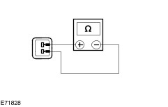
TEST the system for normal operation. | | PINPOINT TEST B : THE SPEED CONTROL DOES NOT DISENGAGE WHEN THE BRAKES ARE APPLIED | | TEST CONDITIONS | DETAILS/RESULTS/ACTIONS | | B1: CHECK THE BPP SWITCH OPERATION | | | 1 Disconnect BPP Switch CCB15. | | | 2 Press the brake pedal. | | | 3 Measure the resistance between the BPP switch CCB15 pin 1, component side and the BPP switch CCB15 pin 2, component side. | | | Is the resistance greater than 10,000 ohms with the brake pedal pressed? Yes No ADJUST the BPP switch. TEST the system for normal operation. If the concern is still evident, INSTALL a new BPP switch. | | B2: CHECK CIRCUIT CCB15 (GN/RD) FOR OPEN CIRCUIT | | | 1 Disconnect CJB CBP02C. | | | 2 Ignition switch in position II. | | | 3 Measure the resistance between the CJB CBP02C pin 3, circuit CCB15 (GN/RD), harness side and the brake pedal position (BPP) switch CCB15 pin 1, circuit CCB15 (GN/RD), harness side. | | | Is the resistance less than 1 ohm? Yes No REPAIR the circuit. TEST the system for normal operation. | | B3: CHECK THE BPP SWITCH FOR GROUND | | | 1 Measure the resistance between the brake pedal position (BPP) switch CCB15 pin 2, circuit GD138 (BK/WH), harness side and ground. | | | Is the resistance less than 1 ohm? Yes INSTALL a new CJB. TEST the system for normal operation. No REPAIR circuit GD138 (BK/WH). TEST the system for normal operation. | | PINPOINT TEST C : THE SPEED CONTROL DOES NOT DISENGAGE WHEN THE CLUTCH IS APPLIED | | TEST CONDITIONS | DETAILS/RESULTS/ACTIONS | | C1: CHECK THE CPP SWITCH OPERATION | | | 1 Disconnect CPP Switch CE903. | | | 2 Press the clutch pedal. | | | 3 Measure the resistance between the CPP switch CE903 pin 1, component side and the CPP switch CE903 pin 2, component side. | | | Is the resistance greater than 10,000 ohms with the clutch pedal pressed? Yes No INSTALL a new CPP switch. TEST the system for normal operation. | | C2: CHECK CIRCUIT CE903 (BU/OG) FOR OPEN CIRCUIT | | | 1 Disconnect CJB CBP02C. | | | 2 Measure the resistance between the CJB CBP02C pin 11, circuit CE903 (BU/OG), harness side and the CPP switch CE903 pin 1, circuit CE903 (BU/OG), harness side. | | | Is the resistance less than 1 ohm? Yes No REPAIR the circuit. TEST the system for normal operation. | | C3: CHECK THE CPP SWITCH FOR GROUND | | | 1 Measure the resistance between the CPP switch CCB15 pin 2, circuit GD138 (BK/WH), harness side and ground. | | | Is the resistance less than 1 ohm? Yes INSTALL a new CJB. TEST the system for normal operation. No REPAIR circuit GD138 (BK/WH). TEST the system for normal operation. | Component Tests - Speed Control Switch Remove the driver air bag.
REFER to: Driver Air Bag Module (501-20B Supplemental Restraint System, Removal and Installation).
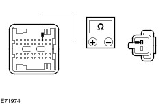
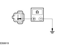
Test 1 Hold the speed control switch in the ON position. Measure the resistance between pin 2 and pin 3. Is the resistance between 1103 ohms and 1128 ohms? If yes, continue with Test 2. If no, INSTALL a new speed control switch. TEST the system for normal operation. Test 2 Hold the speed control switch in the OFF position. Measure the resistance between pin 2 and pin 3. Is the resistance 0 ohms? If yes, continue with Test 3. If no, INSTALL a new speed control switch. TEST the system for normal operation. Test 3 Hold the speed control switch in the SET position. Measure the resistance between pin 2 and pin 3. Is the resistance between 300 ohms and 307 ohms? If yes, continue with Test 4. If no, INSTALL a new speed control switch. TEST the system for normal operation. Test 4 Hold the speed control switch in the RESUME position. Measure the resistance between pin 2 and pin 3. Is the resistance between 598 ohms and 611 ohms? If yes, continue with Test 5. If no, INSTALL a new speed control switch. TEST the system for normal operation. Test 5 Hold the speed control switch in the DECELERATE position. Measure the resistance between pin 2 and pin 3. Is the resistance between 120 ohms and 123 ohms? If yes, INSTALL a new CJB. TEST the system for normal operation. If no, INSTALL a new speed control switch. TEST the system for normal operation. |