| Diagnosis and Testing Refer to Wiring Diagrams Section 415-00, for schematic and connector information. Worldwide Diagnostic System (WDS) Inspection and Verification - Verify the customer concern.
- Visually inspect for obvious signs of mechanical or electrical damage.
Visual Inspection Chart | Mechanical | Electrical | - Audio unit
- Antenna
- Foreign objects contacting speaker
- Trim poorly fitted/resonance
- Audio control switch (if equipped)
| - Fuse(s)
- Wiring harness
- Electrical connector(s)
- Audio unit
- Audio control switch (if equipped)
- Central junction box (CJB)
| - If an obvious cause for an observed or reported concern is found, correct the cause (if possible) before proceeding to the next step.
- If the cause is not visually evident, verify the symptom and refer to the Self-Diagnostic Mode.
Self-Diagnostic Mode NOTE:The audio unit must be in radio mode before entering the Self-Diagnostic Mode. - To enter the audio unit Self-Diagnostic Mode, turn the ignition switch to position II and switch the audio unit ON.
- Press and hold the preset buttons 3 and 5 for 2 seconds, the audio unit will enter the Self-Diagnostic Mode.
- Release the preset buttons 3 and 6, the audio unit will cycle through the tests in the sequence shown in the Self-Diagnostic Mode tables. The duration of each test is 2 seconds.
- To exit the Self-Diagnostic Mode, switch the audio unit OFF.
Self-Diagnostic Mode - 2 Channel System | Message Displayed | Description | | 2 CH COUNT XX | Number of speaker channels. | | 2 CH RF LOW | Right front speaker and circuit low frequency test. | | 2 CH RF HIGH | Right front speaker and circuit high frequency test. | | 2 CH LF LOW | Left front speaker and circuit low frequency test. | | 2 CH LF HIGH | Left front speaker and circuit high frequency test. | | XX.X (frequency) SEEKING | Audio unit searching for an active FM frequency radio station. | | XXXXXXXX (name of radio station) | Active FM frequency radio station found (audible for 2 seconds) | Self-Diagnostic Mode - 4 Channel System | Message Displayed | Description | | 4 CH COUNT XX | Number of speaker channels. | | 4 CH RF LOW | Right front speaker and circuit low frequency test. | | 4 CH RF HIGH | Right front speaker and circuit high frequency test. | | 4 CH LF LOW | Left front speaker and circuit low frequency test. | | 4 CH LF HIGH | Left front speaker and circuit high frequency test. | | 4 CH RR LOW | Right rear speaker and circuit low frequency test. | | 4 CH RR HIGH | Right rear speaker and circuit high frequency test. | | 4 CH LR LOW | Left rear speaker and circuit low frequency test. | | 4 CH LR HIGH | Left rear speaker and circuit high frequency test. | | XX.X (frequency) SEEKING | Audio unit searching for an active FM frequency radio station. | | XXXXXXXX (name of radio station) | Active FM frequency radio station found (audible for 2 seconds). | - If the cause is not evident after the Self-Diagnostic Mode, connect the WDS to the data link connector (DLC).
- Retrieve the Diagnostic Trouble Codes (DTC)s and refer to the DTC Index Chart.
Diagnostic Trouble Code (DTC) Index Chart | DTC | Description/Condition | Possible Source | Action | | U3003 | Battery voltage low | Charging system | REFER to: Charging System (414-00, Diagnosis and Testing). | | P1628 | Ignition state and Controller area network (CAN) messages do not match | CAN | REFER to: Communications Network (418-00 Module Communications Network, Diagnosis and Testing). | | U3000 | Audio unit failure | Audio unit | INSTALL a new audio unit.
REFER to: Audio Unit (415-01 Information and Entertainment System, Removal and Installation).
| | B1A01 | General failure with speakers or speaker circuits | Speakers or speaker circuits | GO to Pinpoint Test C. | | U2100 | Initial configuration not compete | Audio unit configuration | GO to Pinpoint Test F. | | U0155 | Lost communication with instrument cluster | CAN | REFER to: Communications Network (418-00 Module Communications Network, Diagnosis and Testing). | | U0238 | Lost communication with digital audio control module | CAN | REFER to: Communications Network (418-00 Module Communications Network, Diagnosis and Testing). | | U0140 | Lost communication with body control module | CAN | REFER to: Communications Network (418-00 Module Communications Network, Diagnosis and Testing). | | B10BC | Audio control switch voltage out of range | Audio unit control switch or circuits | GO to Pinpoint Test E. | - If the cause is still evident, refer to the Symptom Chart.
Symptom Chart | Symptom | Possible Sources | Action | | The audio unit is inoperative/does not operate correctly | * Circuit. * Audio unit. | * | | The display is blank - radio and CD player operate | * Audio unit. | * INSTALL a new audio unit.
REFER to: Audio Unit (415-01 Information and Entertainment System, Removal and Installation).
TEST the system for normal operation. | | Poor reception | * Antenna. * Antenna cable. * Audio unit. | * | | Poor quality/distorted sound from one or more speakers (not all speakers) | * Speaker(s). * Circuit. * Audio unit. | * | | No sound from all speakers | * Audio unit. | * INSTALL a new audio unit.
REFER to: Audio Unit (415-01 Information and Entertainment System, Removal and Installation).
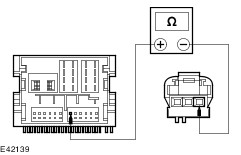
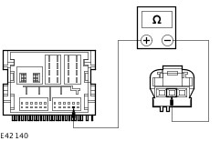
TEST the system for normal operation. | | No sound from one or more of the speakers (not all speakers) | * Speaker(s). * Circuit. * Audio unit. | * | | The audio control switch is inoperative/does not operate correctly. | * Circuit. * Audio control switch. * Audio unit. | * | | The audio unit illumination is inoperative | * Fuse(s). * Circuit(s). * Audio unit. * Central junction box (CJB). | * REFER to: Instrument Cluster and Panel Illumination (413-00 Instrument Cluster and Panel Illumination, Diagnosis and Testing). | | The audio unit clock is not displayed | * Audio unit connector. * Audio unit. * Instrument cluster. | * REFER to: Instrument Cluster (413-01 Instrument Cluster, Diagnosis and Testing). | Pinpoint Tests NOTE:Use a digital multimeter for all electrical measurements. | PINPOINT TEST A : THE AUDIO UNIT IS INOPERATIVE/DOES NOT OPERATE CORRECTLY | | TEST CONDITIONS | DETAILS/RESULTS/ACTIONS | | A1: CHECK FOR POWER TO THE AUDIO UNIT | | | 1 Disconnect Audio Unit CME03B. | | | 2 Ignition switch in position I. | | | 3 Measure the voltage between the audio unit CME03B pin 15, circuit SBP73C (RD), harness side and ground, and between the audio unit CME03B pin 16, circuit SBP82J (RD/BK), harness side and ground. | | | Are the voltages greater than 10 volts? Yes No REPAIR circuit SBP73C (RD) or circuit SBP82J (RD/BK). TEST the system for normal operation. | | A2: CHECK THE AUDIO UNIT GROUND CIRCUITS FOR GROUND | | | 1 Ignition switch in position 0. | | | 2 Measure the resistance between the audio unit CME03B pin 11, circuit GD114J (BK/OG), harness side and ground, and between the audio unit CME03B pin 12, circuit GD114H (BK/OG), harness side and ground. | | | Are the resistances less than 1 ohm? Yes INSTALL a new audio unit.
REFER to: Audio Unit (415-01 Information and Entertainment System, Removal and Installation).
TEST the system for normal operation. No REPAIR circuit GD114J (BK/OG) or circuit GD114H (BK/OG). TEST the system for normal operation. | | PINPOINT TEST B : POOR RECEPTION | | TEST CONDITIONS | DETAILS/RESULTS/ACTIONS | | B1: CHECK THE ANTENNA CABLE SHIELD | | | 1 Ignition switch in position 0. | | | 2 Disconnect the antenna cable from the audio unit. | | | 3 Measure the resistance between the antenna cable ground connector (shield), and ground. | | | Is the resistance less than 1 ohm? Yes No CLEAN and TIGHTEN the antenna base connection to the body. If the concern persists, INSTALL a new antenna cable. TEST the system for normal operation. | | B2: CHECK THE ANTENNA CENTER CONDUCTOR FOR OPEN CIRCUIT | | | 1 Remove the antenna mast. | | | 2 Measure the resistance of the center conductor between the ends of the antenna cable. | | | Is the resistance less than 1 ohm? Yes No INSTALL a new antenna cable. TEST the system for normal operation. | | B3: CHECK ANTENNA CABLE FOR SHORT | | | 1 Measure the resistance between the antenna center conductor and the antenna ground (shield). | | | Is the resistance greater than 10,000 ohms (open circuit)? Yes CLEAN and TIGHTEN the ground connections at the base of the antenna and battery negative cable to the body. If concern the persists, INSTALL a new audio unit.
REFER to: Audio Unit (415-01 Information and Entertainment System, Removal and Installation).
TEST the system for normal operation. No INSTALL a new antenna cable. TEST the system for normal operation. If the concern persists, INSTALL a new audio unit.
REFER to: Audio Unit (415-01 Information and Entertainment System, Removal and Installation).
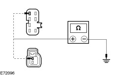
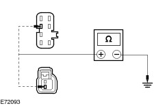
| | PINPOINT TEST C : POOR QUALITY/DISTORTED SOUND FROM ONE OR MORE SPEAKERS (NOT ALL SPEAKERS) | | TEST CONDITIONS | DETAILS/RESULTS/ACTIONS | | C1: CHECK THE SPEAKER RESISTANCE | | | 1 Disconnect Affected Speaker. | | | 2 Measure the resistance between the affected speaker pin 1 and pin 2, component side. | | | Is the resistance approximately 4.0 ohms? Yes No INSTALL a new speaker. TEST the system for normal operation. | | C2: CHECK SPEAKER INPUT FOR SHORT TO GROUND | | | 1 Disconnect Audio Unit CME03A. | | | 2 Measure the resistance between the affected speaker connector pin 1, harness side and ground. | | | Is the resistance greater than 10,000 ohms (open circuit)? Yes No REPAIR speaker input circuit. TEST the system for normal operation. | | C3: CHECK SPEAKER RETURN FOR SHORT TO GROUND | | | 1 Measure the resistance between the affected speaker connector pin 2, harness side and ground. | | | Is the resistance greater than 10,000 ohms (open circuit)? Yes INSTALL a new speaker. TEST the system for normal operation. If the concern persists, INSTALL a new audio unit.
REFER to: Audio Unit (415-01 Information and Entertainment System, Removal and Installation).
No REPAIR speaker return circuit. TEST the system for normal operation. | | PINPOINT TEST D : NO SOUND FROM ONE OR MORE OF THE SPEAKERS (NOT ALL SPEAKERS) | | TEST CONDITIONS | DETAILS/RESULTS/ACTIONS | | D1: CHECK THE SPEAKER RESISTANCE | | | 1 Disconnect Inoperative Speaker. | | | 2 Measure the resistance between the inoperative speaker pin 1 and pin 2, component side. | | | Is the resistance approximately 4.0 ohms? Yes No INSTALL a new speaker(s). TEST the system for normal operation. | | D2: CHECK THE INOPERATIVE SPEAKER(S) CONNECTOR PIN 1 CIRCUIT | | | 1 Disconnect Audio Unit CME03A. | | | 2 Measure the resistance between the following audio unit CME03A pins, harness side and the inoperative speaker(s) connector pin 1, harness side: - (Left front speaker) CME07 pin 1, circuit VME07C (GN/BK) to CME03A pin 3, circuit VME07H (GN/BK).
- (Left rear speaker) CME09 pin 1, circuit VME09F (BN/GN) to CME03A pin 4, circuit VME09E (BN/GN).
- (Right front speaker) CME10 pin 1, circuit VME10C (VT/BK) to CME03A pin 2, circuit VME10J (VT/BK).
- (Right rear speaker) CME12 pin 1, circuit VME12D (BN/WH) to CME03A pin 1, circuit VME12H (BN/WH).
| | | Is the resistance less than 1 ohm? Yes No REPAIR the circuit in question. TEST the system for normal operation. | | D3: CHECK THE INOPERATIVE SPEAKER(S) CONNECTOR PIN 2 CIRCUIT | | | 1 Measure the resistance between the following audio unit CME03A pins, harness side and the inoperative speaker(s) connector pin 2, harness side: - (Left front speaker) CME07 pin 2, circuit RME07A (WH/BN) to CME03A pin 7, circuit RME07D (WH/BN).
- (Left rear speaker) CME09 pin 2, circuit REM09F (BN/YE) to CME03A pin 8, circuit RME09E (BN/YE)
- (Right front speaker) CME10 pin 2, circuit RME10C (WH/OG) to CME03A pin 6, circuit RME10E (WH/OG).
- (Right rear speaker) CME12 pin 2, circuit RME12D (BN/BU) to CME03A pin 5, circuit RME12E (BN/BU).
| | | Is the resistance less than 1 ohm? Yes No REPAIR the circuit in question. TEST the system for normal operation. | | D4: CHECK THE INOPERATIVE SPEAKER(S) CIRCUIT FOR SHORT TO GROUND | | | 1 Measure the resistance between the following inoperative speaker(s) connector pin 1, harness side and ground: - (Left front speaker) CME07 pin 1, circuit VME07A (WH), to ground.
- (Left rear speaker) CME09 pin 1, circuit VME09F (BN/GN), to ground.
- (Right front speaker) CME10 pin 1, circuit VME10C (WH/VT), to ground.
- (Right rear speaker) CME12 pin 1, circuit VME12D (BN/WH), to ground.
| | | Is the resistance greater than 10,000 ohms (open circuit)? Yes INSTALL a new speaker. TEST the system for normal operation. No REPAIR the circuit in question. TEST the system for normal operation. | | PINPOINT TEST E : THE AUDIO CONTROL SWITCH IS INOPERATIVE/DOES NOT OPERATE CORRECTLY | | TEST CONDITIONS | DETAILS/RESULTS/ACTIONS | | E1: CHECK THE AUDIO UNIT OPERATES CORRECTLY USING THE AUDIO UNIT CONTROLS | | | 1 Operate the audio unit using the audio unit controls. | | | Does the audio unit operate correctly using the audio unit controls? Yes If the auxiliary audio control switch is inoperative, GO to E2. No INSTALL a new audio unit.
REFER to: Audio Unit (415-01 Information and Entertainment System, Removal and Installation).
TEST the system for normal operation. | | E2: CHECK THE CIRCUIT VME14A (GY/YE) FOR OPEN | | | 1 Disconnect Audio Unit CME03C. | | | 2 Disconnect Audio Control Switch CME14. | | | 3 Measure the resistance between the audio unit CME03C pin 6, circuit VME14A (GY/YE) harness side and the audio control switch CME14 pin 1, circuit VME14B (GY/YE) harness side. | | | Is the resistance less than 1 ohm? Yes No REPAIR the circuit. TEST the system for normal operation. | | E3: CHECK CIRCUIT RME24A (BU/WH) FOR OPEN | | | 1 Measure the resistance between the audio unit CME14 pin 8, circuit RME24A (BU/WH) harness side and the auxiliary audio control switch CME14 pin 2, circuit RME24B (BU/WH) harness side. | | | Is the resistance less than 1 ohm? Yes INSTALL a new auxiliary audio control switch. TEST the system for normal operation. If the concern persists, INSTALL a new audio unit.
REFER to: Audio Unit (415-01 Information and Entertainment System, Removal and Installation).
No REPAIR the circuit. TEST the system for normal operation. | | PINPOINT TEST F : AUDIO UNIT CONFIGURATION INCOMPLETE | | TEST CONDITIONS | DETAILS/RESULTS/ACTIONS | | F1: CONFIGURE THE AUDIO UNIT TO THE VEHICLE | | | 1 Ignition switch in position III. | | | 2 WAIT for 10 seconds. During this time the audio unit will receive the central configuration data. | | | 3 Ignition switch in position 0. | | | 4 WAIT for 10 seconds. | | | 5 Ignition switch in position III. | | | 6 Using the WDS, CHECK the audio unit for DTC U2100. | | | Is DTC U2100 present? Yes REPEAT the audio unit configuration procedure. If the concern persists,
REFER to: Communications Network (418-00 Module Communications Network, Diagnosis and Testing).
No TEST the system for normal operation. | |