| Diagnosis and Testing Refer to Wiring Diagrams Section 415-00, for schematic and connector information. Worldwide Diagnostic System (WDS) Principles of Operation NOTE:Voice control will only operate with the ignition in position II and the components required switched ON. Voice Control The portable support electronics (PSE) module has a voice control system. The customer will be able to push the MODE button on the audio control switch located on the steering column lower shroud, this will activate the PSE module and allow voice control. An audible noise will be heard through the audio unit speakers after which, a voice command can then be spoken into the microphone located on the A-pillar or cellular phone. The incoming calls and voice confirmation can be heard through the audio system speakers. When a voice command is spoken into the microphone or cellular phone, it will be sent as a signal to the PSE module. The signal is then sent from the PSE module to the relevant components on the medium-speed controller area network (CAN) bus network. The component will then convert the signal back into the original voice command. The components that the PSE module interacts with are as follows: - audio unit
- navigation system display module
- cellular phone
For additional information on the cellular phone system, REFER to the cellular phone Owner's Guide. Bluetooth An input can be given through the cellular phone with or without the cellular phone connected to the handset holder, providing that the cellular phone is supplied with the Bluetooth technology and that the cellular phone is programmed to the PSE module. The Bluetooth technology is a wireless system that interacts with the relevant component modules through the PSE module. The general operation of the Bluetooth is similar to the voice control. Bluetooth technology cannot transfer the cellular phone's PHONEBOOK to the audio unit or navigation system display module. If the cellular phone is placed into the handset holder the PHONEBOOK data will be transferred to the audio unit or navigation system display module. For additional information, REFER to the cellular phone Owner's Guide. Inspection and Verification NOTE: Make sure that the PSE module and cellular phone are configured to each other before starting a system diagnosis. ENTER the following PIN number on the cellular phone to configure the cellular phone to the PSE module: 0000. - Verify the customer concern by operating the system using the customers cellular phone.
- Visually inspect for obvious signs of electrical damage.
Visual Inspection Chart | Electrical | - Fuse(s)
- Wiring harness
- Electrical connector(s)
- Cellular phone
- Microphone
- Handset holder
- PSE module
- Audio unit
- Instrument cluster
- Navigation system display module
| - If an obvious cause for an observed or reported concern is found, correct the cause (if possible) before proceeding to the next step.
- If the cause is not visually evident, connect the WDS to the data link connector (DLC).
- SELECT the ENTERTAINMENT/COMMUNICATION menu.
- SELECT the SPEECH RECOGNITION MODULE option and follow the instructions on the display.
- Retrieve the diagnostic trouble codes (DTC)s and refer to the DTC Index Chart.
- If no DTCs are retrieved or there is no communication with the module, proceed to the Symptom Chart to continue diagnostics.
Diagnostic Trouble Code (DTC) Index Chart | DTC | Description/Condition | Possible Source | Action | | B1039 | Microphone input circuit failure | Microphone defect or short to ground | GO to Pinpoint Test C. | | B1317 | Battery voltage high | Battery voltage above 16 volts | REFER to: Charging System (414-00 Charging System - General Information, Diagnosis and Testing). | | B1318 | Battery voltage low | Battery voltage below 9 volts | REFER to: Charging System (414-00 Charging System - General Information, Diagnosis and Testing). | | B1342 | PSE module failure | PSE module | INSTALL a new PSE module.
REFER to: Portable Support Electronics (PSE) Module (415-01 Information and Entertainment System, Removal and Installation).
TEST the system for normal operation. | | B1899 | Microphone input signal circuit open | Microphone defect or not connected | GO to Pinpoint Test C. | | B2272 | Microphone bias circuit failure | No supply to microphone | GO to Pinpoint Test C. | | B2288 | PSE module error | PSE module | INSTALL a new PSE module.
REFER to: Portable Support Electronics (PSE) Module (415-01 Information and Entertainment System, Removal and Installation).
TEST the system for normal operation. | | B2477 | Faulty module configuration | PSE module | REFER to the WDS. | | P1619 | Total checksum error | PSE module | INSTALL a new PSE module.
REFER to: Portable Support Electronics (PSE) Module (415-01 Information and Entertainment System, Removal and Installation).
TEST the system for normal operation. | | P2503 | Charging system voltage low | Short to ground | GO to Pinpoint Test B. | | U0074 | Bluetooth communication failure to cellular phone | PSE module or cellular phone | CHECK the cellular phone Bluetooth function with another application to determine if the cellular phone is the concern. If the Bluetooth function operates correctly with the other application, INSTALL a new PSE module.
REFER to: Portable Support Electronics (PSE) Module (415-01 Information and Entertainment System, Removal and Installation).
TEST the system for normal operation. If the Bluetooth function does not operate with other application, REFER to the cellular phone Owner's Guide. | | U2050 | No application present | PSE module | INSTALL a new PSE module.
REFER to: Portable Support Electronics (PSE) Module (415-01 Information and Entertainment System, Removal and Installation).
TEST the system for normal operation. | - If the cause is not evident, refer to the Symptom Chart.
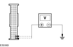
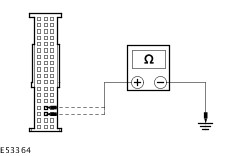
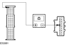
Symptom Chart | Symptom | Possible Sources | Action | | No communication with the portable support electronics (PSE) module | * Fuse(s). * Circuit(s). * PSE module. | * | | * DLC. | * REFER to: Communications Network (418-00 Module Communications Network, Diagnosis and Testing). | | The audio unit display does not display PHONE | * Instrument cluster. * Audio unit. * Navigation system display module. * PSE module. | * CHECK all communication between the instrument cluster, audio unit, navigation system display module and PSE module. REFER to the WDS. | | The handset battery does not charge | * Fuse(s). * Circuit(s). * PSE module. * Handset holder. | * | | * Cellular phone battery. | * REFER to the cellular phone Owner's Guide. | | The cellular phone microphone is not operating correctly | * Circuit(s). * Microphone. * PSE module. | * | | Reduced sound or no sound through the speakers | * Instrument cluster. * Audio unit. * Navigation system display module. * PSE module. | * CHECK all communication between the instrument cluster, audio unit, navigation system display module and PSE module. REFER to the WDS. | | * Circuit(s). * Audio unit. * PSE module. | * | | The cellular phone information is not displayed | * Instrument cluster. * Audio unit. * Navigation system display module. * PSE module. | * CHECK all communication between the instrument cluster, audio unit, navigation system display module and PSE module. REFER to the WDS. | | The voice activated phone functions are inoperative | * Instrument cluster. * Audio unit. * Navigation system display module. * PSE module. | * CHECK all communication between the instrument cluster, audio unit, navigation system display module and PSE module. REFER to the WDS. | | * Circuit(s). * Cellular Phone. * Handset holder. * PSE module. | * | Pinpoint Tests NOTE:ENTER the following PIN number on the cellular phone to configure the cellular phone to the PSE module: 0000. NOTE:Use a digital multimeter for all electrical measurements. | PINPOINT TEST A : NO COMMUNICATION WITH THE PORTABLE SUPPORT ELECTRONICS (PSE) MODULE | | TEST CONDITIONS | DETAILS/RESULTS/ACTIONS | | A1: CHECK FOR VOLTAGE AT THE PSE MODULE | | | 1 Disconnect PSE Module CMM08A. | | | 2 Measure the voltage between the PSE module CMM08A pin 17, circuit SBP73F (RD), harness side and ground; and the PSE module CMM08A pin 18, circuit SBP73E (RD), harness side and ground. | | | Are the voltages greater than 10 volts? Yes No REPAIR circuit SBP73F (RD) or circuit SBP73E (RD) as necessary. TEST the system for normal operation. | | A2: CHECK THE PSE MODULE GROUND CIRCUIT(S) | | | 1 Measure the resistance between the PSE module CMM08A pin 33, circuit GD114F (BK/BU), harness side and ground; and the PSE module CMM08A pin 34, circuit GD114H (BK/BU), harness side and ground. | | | Are the resistances less than 1 ohm? Yes INSTALL a new PSE module.
REFER to: Portable Support Electronics (PSE) Module (415-01 Information and Entertainment System, Removal and Installation).
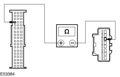
TEST the system for normal operation. No REPAIR circuit GD114F (BK/BU) or circuit GD114H (BK/BU) as necessary. TEST the system for normal operation. | | PINPOINT TEST B : THE HANDSET BATTERY DOES NOT CHARGE | | TEST CONDITIONS | DETAILS/RESULTS/ACTIONS | | B1: CHECK THE CELLULAR PHONE DISPLAY WHEN BEING USED OUTSIDE OF THE VEHICLE | | | 1 Operate the cellular phone outside of the vehicle. | | | Does the cellular phone display low battery? Yes No CHECK the cellular phone battery. REFER to the cellular phone Owner's Guide. | | B2: CHECK THE BATTERY SYMBOL ON CELLULAR PHONE | | | 1 Ignition switch in position II. | | | INSTALL the cellular phone into the handset holder. Does the battery symbol flash? Yes Cellular phone battery charging correctly. WAIT for the cellular phone battery to charge. TEST the system for normal operation. No | | B3: CHECK FOR VOLTAGE AT THE PSE MODULE | | | 1 Disconnect PSE Module CMM08A. | | | 2 Measure the voltage between the PSE module CMM08A pin 17, circuit SBP73E (RD), harness side and ground; and the PSE module CMM08A pin 18, circuit SBP73F (RD), harness side and ground. | | | Are the voltages greater than 10 volts? Yes No REPAIR circuit SBP73E (RD) or circuit SBP73F (RD) as necessary. TEST the system for normal operation. | | B4: CHECK THE PSE MODULE GROUND CIRCUIT(S) | | | 1 Measure the resistance between the PSE module CMM08A pin 33, circuit GD114G (BK/BU), harness side and ground; and the PSE module CMM08A pin 34, circuit GD114H (BK/BU), harness side and ground. | | | Are the resistances less than 1 ohm? Yes No REPAIR circuit GD114G (BK/BU) or circuit GD114H (BK/BU) as necessary. TEST the system for normal operation. | | B5: CHECK FOR CHARGE VOLTAGE AT THE HANDSET HOLDER | | | 1 Connect PSE Module CMM08A. | | | 2 Disconnect Handset Holder CMM01A. | | | 3 Measure the voltage between the handset holder CMM01A pin 15, circuit CMM03A (VT), harness side and ground. | | | Is the voltage greater than 10 volts? Yes No NOTE: If the connector is damaged install a new harness. REPAIR the circuit CMM03A (VT). TEST the system for normal operation. | | B6: CHECK GROUND CIRCUIT LMM17A (WH/BU) | | | 1 Measure the resistance between the handset holder CMM01A pin 8, circuit LMM17A (WH/BU), harness side and ground. | | | Is the resistance less than 1 ohm? Yes No REPAIR the circuit. TEST the system for normal operation. | | B7: CHECK FOR VOLTAGE AT CIRCUIT RMM17A (GN/BU) | | | 1 Measure the voltage between the handset holder CMM01A pin 7, circuit RMM17A (GN/BU), harness side and ground. | | | Is the voltage greater than 10 volts? Yes INSTALL a new PSE module.
REFER to: Portable Support Electronics (PSE) Module (415-01 Information and Entertainment System, Removal and Installation).
TEST the system for normal operation. No REPAIR the circuit. TEST the system for normal operation. If the concern persists, INSTALL a new handset holder.
REFER to: Handset Holder (415-01 Information and Entertainment System, Removal and Installation).
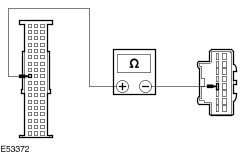
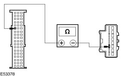
TEST the system for normal operation. | | PINPOINT TEST C : THE CELLULAR PHONE MICROPHONE IS NOT OPERATING CORRECTLY | | TEST CONDITIONS | DETAILS/RESULTS/ACTIONS | | C1: CHECK THAT THE VOICE IS BEING TRANSMITTED DURING A TELEPHONE CONVERSION OUTSIDE OF THE VEHICLE | | | 1 Operate the cellular phone outside the vehicle. | | | Does the cellular phone transmit the voice during a telephone conversation outside of the vehicle? Yes No REFER to the cellular phone Owner's Guide. | | C2: CHECK CIRCUIT RMM13A (BU) FOR OPEN | | | 1 Disconnect PSE Module CMM08A. | | | 2 Disconnect Microphone CMM13. | | | 3 Measure the resistance between the PSE module CMM08A pin 3, circuit RMM13A (BU), harness side and the microphone CMM13 pin 1, circuit RMM13A (BU), harness side. | | | Is the resistance less than 1 ohm? Yes No REPAIR the circuit. TEST the system for normal operation. | | C3: CHECK CIRCUIT VMM13A (YE/GN) FOR OPEN | | | 1 Measure the resistance between the PSE module CMM08A pin 4, circuit VMM13A (YE/GN), harness side and the microphone CMM13 pin 2, circuit VMM13A (YE/GN), harness side. | | | Is the resistance less than 1 ohm? Yes INSTALL a new microphone. TEST the system for normal operation. No REPAIR the circuit. TEST the system for normal operation. If the concern persists, INSTALL a new PSE module.
REFER to: Portable Support Electronics (PSE) Module (415-01 Information and Entertainment System, Removal and Installation).
TEST the system for normal operation. | | PINPOINT TEST D : REDUCED SOUND OR NO SOUND THROUGH THE SPEAKERS | | TEST CONDITIONS | DETAILS/RESULTS/ACTIONS | | D1: CHECK THE CELLULAR PHONE OPERATES CORRECTLY OUTSIDE THE VEHICLE | | | 1 CARRY OUT an audio unit self-test.
REFER to: Audio System (415-00 Information and Entertainment System - General Information, Diagnosis and Testing).
| | | 2 Operate the cellular phone outside the vehicle. | | | Does the cellular phone operate correctly outside the vehicle? Yes No REFER to the cellular phone Owner's Guide. | | D2: CHECK CIRCUIT VMM06A (GN/VT) FOR OPEN | | | 1 Disconnect PSE Module CMM08A. | | | 2 Disconnect Audio Unit CME03C. | | | 3 Measure the resistance between the PSE module CMM08A pin 1, circuit VMM06A (GN/VT), harness side and the audio unit CME03C pin 1, circuit VMM06A (GN/VT), harness side. | | | Is the resistance less than 1 ohm? Yes No REPAIR the circuit. TEST the system for normal operation. | | D3: CHECK CIRCUIT VMM04A (WH/OG) FOR OPEN | | | 1 Measure the resistance between the PSE module CMM08A pin 2, circuit VMM04A (WH/OG), harness side and the audio unit CME03C pin 7, circuit VMM04A (WH/OG), harness side. | | | Is the resistance less than 1 ohm? Yes INSTALL a new PSE module.
REFER to: Portable Support Electronics (PSE) Module (415-01 Information and Entertainment System, Removal and Installation).
TEST the system for normal operation. No REPAIR the circuit. TEST the system for normal operation. If the concern persists,
REFER to: Audio System (415-00 Information and Entertainment System - General Information, Diagnosis and Testing).
| | PINPOINT TEST E : THE VOICE ACTIVATED PHONE FUNCTIONS ARE INOPERATIVE | | TEST CONDITIONS | DETAILS/RESULTS/ACTIONS | | E1: CHECK CIRCUIT VMM21A (GY/OG) FOR OPEN | | | 1 Disconnect PSE Module CMM08B. | | | 2 Disconnect Handset Holder CMM01A. | | | 3 Measure the resistance between the PSE module CMM08B pin 45, circuit VMM21A (GY/OG), harness side and the handset holder CMM01A pin 4, circuit VMM21A (GY/OG), harness side. | | | Is the resistance less than 1 ohm? Yes No REPAIR the circuit. TEST the system for normal operation. | | E2: CHECK CIRCUIT VMM02A (GY/VT) FOR OPEN | | | 1 Measure the resistance between the PSE module CMM08B pin 47, circuit VMM02A (GY/VT), harness side and the handset holder CMM01A pin 1, circuit VMM02A (GY/VT), harness side. | | | Is the resistance less than 1 ohm? Yes No REPAIR the circuit. TEST the system for normal operation. | | E3: CHECK CIRCUIT RMM02A (BU/WH) FOR OPEN | | | 1 Measure the resistance between the PSE module CMM08B pin 48, circuit RMM02A (BU/WH), harness side and the handset holder CMM01A pin 9, circuit RMM02A (BU/WH), harness side. | | | Is the resistance less than 1 ohm? Yes No REPAIR the circuit. TEST the system for normal operation. | | E4: CHECK CIRCUIT VMM01A (BN/GN) FOR OPEN | | | 1 Measure the resistance between the PSE module CMM08B pin 49, circuit VMM01A (BN/GN), harness side and the handset holder CMM01A pin 2, circuit VMM01A (BN/GN), harness side. | | | Is the resistance less than 1 ohm? Yes No REPAIR the circuit. TEST the system for normal operation. | | E5: CHECK CIRCUIT RMM01A (BN/WH) FOR OPEN | | | 1 Measure the resistance between the PSE module CMM08B pin 50, circuit RMM01A (BN/WH), harness side and the handset holder CMM01A pin 10, circuit RMM01A (BN/WH), harness side. | | | Is the resistance less than 1 ohm? Yes No REPAIR the circuit. TEST the system for normal operation. | | E6: CHECK CIRCUIT LMM18A (GN/WH) FOR OPEN | | | 1 Measure the resistance between the PSE module CMM08B pin 42, circuit LMM18A (GN/WH), harness side and the handset holder CMM01A pin 3, circuit LMM18A (GN/WH), harness side. | | | Is the resistance less than 1 ohm? Yes No REPAIR the circuit. TEST the system for normal operation. | | E7: CHECK CIRCUIT CMM19A (BN/YE) FOR OPEN | | | 1 Measure the resistance between the PSE module CMM08B pin 41, circuit CMM19A (BN/YE), harness side and the handset holder CMM01A pin 11, circuit CMM19A (BN/YE), harness side. | | | Is the resistance less than 1 ohm? Yes No REPAIR the circuit. TEST the system for normal operation. | | E8: CHECK CIRCUIT VMM20A (GN/BN) FOR OPEN | | | 1 Measure the resistance between the PSE module CMM08B pin 51, circuit VMM20A (GN/BN), harness side and the handset holder CMM01A pin 12, circuit VMM20A (GN/BN), harness side. | | | Is the resistance less than 1 ohm? Yes No REPAIR the circuit. TEST the system for normal operation. | | E9: CHECK CIRCUIT VMM09A (YE/GY) FOR OPEN | | | 1 Measure the resistance between the PSE module CMM08B pin 37, circuit VMM09A (YE/GY), harness side and the handset holder CMM01A pin 5, circuit VMM09A (YE/GY), harness side. | | | Is the resistance less than 1 ohm? Yes No REPAIR the circuit. TEST the system for normal operation. | | E10: CHECK CIRCUIT RMM09A (BU/GN) FOR OPEN | | | 1 Measure the resistance between the PSE module CMM01B pin 38, circuit RMM09A (BU/GN), harness side and the handset holder CMM17A pin 13, circuit RMM09A (BU/GN), harness side. | | | Is the resistance less than 1 ohm? Yes No REPAIR the circuit. TEST the system for normal operation. | | E11: CHECK CIRCUIT RMM12A (VT/BN) FOR OPEN | | | 1 Measure the resistance between the PSE module CMM08B pin 39, circuit RMM12A (VT/BN), harness side and the handset holder CMM01A pin 6, circuit RMM12A (VT/BN), harness side. | | | Is the resistance less than 1 ohm? Yes No REPAIR the circuit. TEST the system for normal operation. | | E12: CHECK CIRCUIT VMM12A (WH/BN) FOR OPEN | | | 1 Measure the resistance between the PSE module CMM08B pin 40, circuit VMM12A (WH/BN), harness side and the handset holder CMM01A pin 14, circuit VMM12A (WH/BN), harness side. | | | Is the resistance less than 1 ohm? Yes INSTALL a new PSE module.
REFER to: Portable Support Electronics (PSE) Module (415-01 Information and Entertainment System, Removal and Installation).
TEST the system for normal operation. No REPAIR the circuit. TEST the system for normal operation. If the concern persists, INSTALL a new handset holder.
REFER to: Handset Holder (415-01 Information and Entertainment System, Removal and Installation).
TEST the system for normal operation. | |