| PINPOINT TEST B : ONE OR MORE SIDE LIGHTS (PARKING LIGHTS) FRONT/REAR, LICENSE PLATE LAMPS OR ADDITIONAL SIDE LIGHTS INOPERATIVE |
| TEST CONDITIONS | DETAILS/RESULTS/ACTIONS |
| B1: DETERMINE THE FAULT CONDITION |
| | 1 CHECK the side lights (parking lights). |
| | 2 CHECK the side lights (parking lights) front/rear, license plate lamps and/or all additional side lights. |
| | Are the license plate lamps and, if fitted, the rear additional side lights or the side and rear additional side lights inoperative? Yes - Vehicles without autolamps: Both rear side lights (parking lights) are inoperative (platform truck): LOCATE and RECTIFY the break in circuit B_GD129J/T/S (BK/YE) between soldered connection S4D129G and soldered connection S1D129E, with the aid of the Wiring Diagrams. CHECK the operation of the system. - Vehicles with autolamps: Both rear side lights (parking lights) are inoperative: GO to B2. - Left-hand rear side side light (parking light) is inoperative: GO to B3. - Right-hand rear side light (parking light) is inoperative: GO to B5. - Vehicles with tailgate and autolamps: Both license plate lamps are inoperative: GO to B7. - Vehicles with rear doors, autolamps and side lights/turn signal lamps: Both license plate lamps are inoperative: GO to B9. - One license plate lamp is inoperative (platform truck): GO to B11. - One license plate lamp is inoperative (box van, bus, combi): GO to B12. - One rear additional side light is inoperative: GO to B14. - One rear and center side light is inoperative (platform truck): GO to B16. - One rear and center side light is inoperative (box van, bus, combi): GO to B18. - Left and right-hand center side lights are inoperative (platform truck): GO to B20. - Left and right-hand rear side lights are inoperative (platform truck): GO to B21. - Both rear additional side lights and, if fitted, all left and right-hand side lights inoperative (platform truck): LOCATE and RECTIFY the break in circuit B_GD129AA(W)(K) (BK/YE), between soldered connection S4D129B and soldered connection S1D129E, with the aid of the Wiring Diagrams. CHECK the operation of the system. - Both license plate lamps and, if fitted, both rear additional side lights and all left and right-hand side lights inoperative (platform truck): GO to B22. - Left-hand rear and center side lights and both license plate lamps are inoperative (box van, bus, combi): LOCATE and RECTIFY the break in circuit CBP79B(D) (VT/WH), between soldered connection S2BP79 and soldered connection S4BP79E, with the aid of the Wiring Diagrams. CHECK the operation of the system. - Right-hand rear and center side lights are inoperative (box van, bus, combi): LOCATE and RECTIFY the break in circuit CBP79C(M) (VT/WH), between soldered connection S2BP79 and soldered connection S4BP79F, with the aid of the Wiring Diagrams. CHECK the operation of the system. No - Box van, bus, combi, without front side light/turn signal lamp: Left-hand front side light (parking light) inoperative: LOCATE and RECTIFY the break in circuit CBP76B (BU/BN), between soldered connection S2BP76 and the left-hand headlamp, with the aid of the Wiring Diagrams. CHECK the operation of the system. If necessary INSTALL a new headlamp. CHECK the operation of the system. - Left-hand front side light (parking light), left-hand front side light/turn signal lamp are inoperative: LOCATE and RECTIFY the break in circuit CBP76B(E)(F) (BU/BN), between soldered connection S2BP76 and soldered connection S1BP76, with the aid of the Wiring Diagrams. CHECK the operation of the system. - Vehicles with front side light/turn signal lamp: Left-hand front side light (parking light) inoperative (left-hand side light/turn signal lamp OK): LOCATE and RECTIFY the break in circuit CBP76E(F) (BU/BN), between soldered connection S1BP76 and the left-hand headlamp, with the aid of the Wiring Diagrams. CHECK the operation of the system. If necessary INSTALL a new headlamp. CHECK the operation of the system. - Left-hand front side light/turn signal lamp is inoperative: GO to B25. - Left-hand front clearance lamp is inoperative: GO to B27. - Box van, bus, combi, without front side light/turn signal lamp: Right-hand front side light (parking lights) inoperative: LOCATE and RECTIFY the break in circuit CBP75 (YE/GY), between soldered connection S2BP75 and the right-hand headlamp, with the aid of the Wiring Diagrams. CHECK the operation of the system. If necessary INSTALL a new headlamp. CHECK the operation of the system. - Vehicles without front clearance lamps: Right-hand front side light (parking lights), right-hand front side light/turn signal lamp are inoperative: LOCATE and RECTIFY the break in circuit CBP75B(E)(F) (YE/GY), between soldered connection S2BP75 and soldered connection S1BP75, with the aid of the Wiring Diagrams. CHECK the operation of the system. - Platform truck with autolamps, side lights/turn signal lamps and front clearance lamps: Right-hand front side light (parking lights), right-hand front side light/turn signal lamp are inoperative: LOCATE and RECTIFY the break in circuit CBP75B(E) (YE/GY), between soldered connection S2BP75 and soldered connection S1BP75, with the aid of the Wiring Diagrams. CHECK the operation of the system. - Platform truck with autolamps, side lights/turn signal lamps and front clearance lamps: Right-hand front side light (parking lights), right-hand front side light/turn signal lamp and right-hand front clearance lamps are inoperative: GO to B33. - Vehicles with front side light/turn signal lamp and, if fitted, front clearance lamps: Right-hand front side light (parking lights) inoperative (right-hand side light/turn signal lamp and right-hand front clearance lamps OK): LOCATE and RECTIFY the break in circuit CBP75E(F) (YE/GY), between soldered connection S1BP75 and the right-hand headlamp, with the aid of the Wiring Diagrams. CHECK the operation of the system. If necessary INSTALL a new headlamp. CHECK the operation of the system. - Right-hand front side light/turn signal lamp is inoperative: GO to B29. - Right-hand front clearance lamp is inoperative: GO to B31. - Platform truck with autolamps, side lights/turn signal lamps and front clearance lamps: Left-hand front side light (parking lights), left/right-hand rear parking lamp, left-hand front side light/turn signal lamp and left-hand front clearance lamps are inoperative: GO to B36. - Vehicles with or without front side light/turn signal lamp: Left-hand front side light (parking lights), left-hand rear parking lamp and left-hand front side light/turn signal lamp are inoperative: GO to B36. - Vehicles with or without front side light/turn signal lamp: Right-hand front side light (parking lights), right-hand rear parking lamp and right-hand front side light/turn signal lamp are inoperative: GO to B39. |
| B2: CHECK GROUND CONNECTION TO REAR LAMP ASSEMBLY FOR OPEN CIRCUIT |
| | 1 Ignition switch in position 0. |
| | 2 SWITCH OFF the side lights (parking lights). |
| | 3 Disconnect Left-hand rear lamp assembly from connector CLS04. |
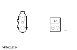
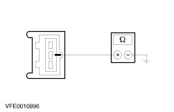
| | 4 Measure the resistance between the left-hand rear lamp assembly, connector CLS04, pin 1, circuit B_GD129U (BK/YE), wiring harness side and ground. |
| | Is a resistance of less than 2 Ohm registered? Yes LOCATE and RECTIFY the break in circuit CBP76D(J)(K)(L) (BU/BN) between soldered connection S2BP76 and soldered connection S4BP76, with the aid of the Wiring Diagrams. CHECK the operation of the system. No LOCATE and RECTIFY the break in circuit B_GD129J(T)(S) (BK/YE) between soldered connection S4D129G and soldered connection S1D129E, with the aid of the Wiring Diagrams. CHECK the operation of the system. |
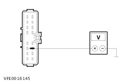
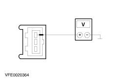
| B3: CHECK VOLTAGE SUPPLY TO LEFT-HAND REAR LAMP ASSEMBLY FOR OPEN CIRCUIT |
| | 1 Ignition switch in position 0. |
| | 2 SWITCH OFF the side lights (parking lights). |
| | 3 Disconnect Left-hand rear lamp assembly. - Box van, bus, combi: from connector CLS22
- Platform truck: from connector CLS04
|
| | 4 SWITCH ON the side lights (parking lights). |
| | 5 Box van, bus, combi: |
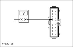
| | 6 Measure the voltage between the left-hand rear lamp assembly, connector CLS22, pin 3, circuit CBP76F(H) (BU/BN), wiring harness side and ground. |
| | 7 Platform truck: |
| | 8 Measure the voltage between the left-hand rear lamp assembly, connector CLS04, pin 3, circuit CBP76L(N) (BU/BN), wiring harness side and ground. |
| | Is battery voltage measured? Yes No - Vehicles with autolamps: LOCATE and RECTIFY the break in the circuit between soldered connection S4BP76 and the left-hand rear lamp assembly with the aid of the Wiring Diagrams. CHECK the operation of the system. - All other models: LOCATE and RECTIFY the break in the circuit between soldered connection S2BP76 and the left-hand rear lamp assembly with the aid of the Wiring Diagrams. CHECK the operation of the system. |
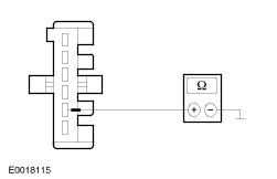
| B4: CHECK GROUND CONNECTION TO LEFT-HAND REAR LAMP ASSEMBLY FOR OPEN CIRCUIT |
| | 1 SWITCH OFF the side lights (parking lights). |
| | 2 Box van, bus, combi: |
| | 3 Measure the resistance between the left-hand rear lamp assembly, connector CLS22, pin 5, circuit B-GD149B(R) (BK/GY), wiring harness side, and ground. |
| | 4 Platform truck: |
| | 5 Measure the resistance between the left-hand rear lamp assembly, connector CLS04, pin 1, circuit B-GD129U (BK/YE), wiring harness side, and ground. |
| | Is a resistance of less than 2 Ohm registered? Yes CHECK and if necessary INSTALL a new left-hand rear lamp assembly. CHECK the operation of the system. No - Box van, bus, combi: LOCATE and RECTIFY the break in the circuit between the left-hand rear lamp assembly and ground connection GP49 with the aid of the Wiring Diagrams. CHECK the operation of the system. - Platform truck: LOCATE and RECTIFY the break in the circuit between the left-hand rear lamp assembly and soldered connection S4D129G with the aid of the Wiring Diagrams. CHECK the operation of the system. |
| B5: CHECK VOLTAGE SUPPLY TO RIGHT-HAND REAR LAMP ASSEMBLY FOR OPEN CIRCUIT |
| | 1 Ignition switch in position 0. |
| | 2 SWITCH OFF the side lights (parking lights). |
| | 3 Disconnect Right-hand rear lamp assembly from connector CLS26. |
| | 4 SWITCH ON the side lights (parking lights). |
| | 5 Box van, bus, combi: |
| | 6 Measure the voltage between the right-hand rear lamp assembly, connector CLS26, pin 3, circuit CBP75(D) (YE/GY), wiring harness side, and ground. |
| | 7 Platform truck: |
| | 8 Measure the voltage between the right-hand rear lamp assembly: - Platform truck without autolamps: connector CLS26, pin 3, circuit CBP75L (YE/GY), wiring harness side, and ground.
- Platform truck with autolamps: connector CLS26, pin 3, circuit CBP76M (BU/BN), wiring harness side, and ground.
|
| | Is battery voltage measured? Yes No - Vehicles with autolamps: LOCATE and RECTIFY the break in the circuit between soldered connection S4BP76 and the right-hand rear lamp assembly with the aid of the Wiring Diagrams. CHECK the operation of the system. - All other models: LOCATE and RECTIFY the break in the circuit between soldered connection S2BP75 and the right-hand rear lamp assembly with the aid of the Wiring Diagrams. CHECK the operation of the system. |
| B6: CHECK GROUND CONNECTION TO RIGHT-HAND REAR LAMP ASSEMBLY FOR OPEN CIRCUIT |
| | 1 SWITCH OFF the side lights (parking lights). |
| | 2 Box van, bus, combi: |
| | 3 Measure the resistance between the right-hand rear lamp assembly, connector CLS26, pin 5, circuit A-GD151AA(K) (BK/GN), wiring harness side, and ground. |
| | 4 Platform truck: |
| | 5 Measure the resistance between the right-hand rear lamp assembly, connector CLS26, pin 1, circuit B-GD129V (BK/YE), wiring harness side, and ground. |
| | Is a resistance of less than 2 Ohm registered? Yes CHECK and if necessary INSTALL a new right-hand rear lamp assembly. CHECK the operation of the system. No - Box van, bus, combi: LOCATE and RECTIFY the break in the circuit between the right-hand rear lamp assembly and ground connection GP51 with the aid of the Wiring Diagrams. CHECK the operation of the system. - Platform truck: LOCATE and RECTIFY the break in the circuit between the right-hand rear lamp assembly and soldered connection S4D129G with the aid of the Wiring Diagrams. CHECK the operation of the system. |
| B7: CHECK FUSE F79 (7.5 A) (CJB). |
| | 1 Disconnect Fuse F79 (7.5 A) (CJB). |
| | 2 CHECK Fuse F79 (7.5 A) (CJB). |
| | Is the fuse OK? Yes No INSTALL a new fuse F79 (7.5 A) (CJB) and CHECK the operation of the system. If the fuse blows again, LOCATE and RECTIFY the short to ground with the aid of the Wiring Diagrams. CHECK the operation of the system. |
| B8: CHECK THE VOLTAGE SUPPLY TO FUSE F79 (7.5 A) (CJB) FOR OPEN CIRCUIT |
| | 1 Connect Fuse F79 (7.5 A) (CJB). |
| | 2 Measure the voltage between fuse F79 (7.5 A) (CJB) and ground. |
| | Is battery voltage measured? Yes No LOCATE and RECTIFY the break in the voltage supply of fuse F79 (7.5 A) (CJB) with the aid of the Wiring Diagrams. If necessary INSTALL a new central junction box (CJB). CHECK the operation of the system. |
| B9: CHECK THE POWER SUPPLY TO THE LICENSE PLATE LAMPS FOR OPEN CIRCUIT |
| | 1 Ignition switch in position 0. |
| | 2 SWITCH OFF the side lights (parking lights). |
| | 3 Disconnect License plate lamp on left-hand side. - Vehicles with rear doors: from connector CLS04
- Vehicles with tailgate: from connector CLS04L
|
| | 4 SWITCH ON the side lights (parking lights). |
| | 5 Vehicles with rear doors: |
| | 6 Measure the voltage between the left-hand license plate lamp, connector CLS04, pin 1, circuit CBP79H (VT/WH)/CBP79J (VT/WH), wiring harness side and ground. |
| | 7 Vehicles with tailgate: |
| | 8 Measure the voltage between the left-hand license plate lamp, connector CLS04L, pin 1, circuit CBP79G (VT/WH) wiring harness side, and ground. |
| | Is battery voltage measured? Yes - Vehicles with tailgate: LOCATE and RECTIFY the break in the circuit between soldered connection S9D149B and ground connection GP49 with the aid of the Wiring Diagrams. CHECK the operation of the system. - Vehicles with rear doors and side lights/turn signal lamps: LOCATE and RECTIFY the break in the circuit between soldered connection S4D149J and ground connection GP49 with the aid of the Wiring Diagrams. CHECK the operation of the system. No - All other vehicles: LOCATE and RECTIFY the break in circuit CBP79F(H) (VT/WH) between soldered connection S4BP79E and the left-hand license plate lamp with the aid of the Wiring Diagrams. CHECK the operation of the system. |
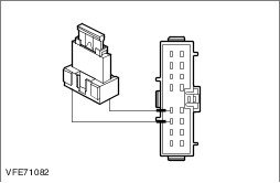
| B10: CHECK CIRCUIT CBP79A(D)(E)(F) (VT/WH) BETWEEN CENTRAL JUNCTION BOX (CJB) AND SOLDERED CONNECTION S4BP79 FOR BREAKS |
| | 1 Disconnect Central junction box (CJB) from connector CBP02B. |
| | 2 Measure the resistance between the central junction box (CJB), connector CBP02B, pin 16, circuit CBP79A (VT/WH), wiring harness side and left-hand license plate lamp, connector CLS04L, pin 1, circuit CBP79G (VT/WH), wiring harness side. |
| | Is a resistance of less than 2 Ohm registered? Yes INSTALL a new central junction box (CJB). CHECK the operation of the system. No LOCATE and RECTIFY the break in the circuit between the central junction box (CJB) and soldered connection S4BP79 with the aid of the Wiring Diagrams. CHECK the operation of the system. |
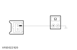
| B11: CHECK GROUND CONNECTION TO INOPERATIVE LICENSE PLATE LAMP FOR OPEN CIRCUIT |
| | 1 Ignition switch in position 0. |
| | 2 SWITCH OFF the side lights (parking lights). |
| | 3 Disconnect Inoperative license plate lamp. - left: from connector CLS22B
- right: from connector CLS22A
|
| | 4 Measure the resistance at the inoperative license plate lamp: - left: connector CLS22B, pin 2, circuit B_GD129AB (BK/YE), wiring harness side, and ground.
- right: connector CLS22A, pin 2, circuit B_GD129Y (BK/YE), wiring harness side, and ground.
|
| | Is a resistance of less than 2 Ohm registered? Yes - Vehicles with additional side lights: CHECK the inoperative license plate lamp and if necessary INSTALL a new one. CHECK the operation of the system. No LOCATE and RECTIFY the break in the circuit between the inoperative license plate lamp and soldered connection S4D129B with the aid of the Wiring Diagrams. CHECK the operation of the system. |
| B12: CHECK GROUND CONNECTION TO INOPERATIVE LICENSE PLATE LAMP FOR OPEN CIRCUIT |
| | 1 Ignition switch in position 0. |
| | 2 SWITCH OFF the side lights (parking lights). |
| | 3 Disconnect Inoperative license plate lamp. - left, vehicles with rear doors: from connector CLS04
- left, vehicles with tailgate: from connector CLS04L
- right, vehicles with rear doors: from connector CLS05
- right, vehicles with tailgate: from connector CLS05L
|
| | 4 Vehicles with rear doors: |
| | 5 Measure the resistance between the inoperative license plate lamp: - left: connector CLS04, pin 2, circuit B_GD149F (BK/GY), wiring harness side, and ground.
- right: connector CLS05, pin 2, circuit B_GD149E (BK/GY), wiring harness side, and ground.
|
| | 6 Vehicles with tailgate: |
| | 7 Measure the resistance between the inoperative license plate lamp: - left: connector CLS04L, pin 2, circuit B_GD149V (BK/GY), wiring harness side, and ground.
- right: connector CLS05L, pin 2, circuit B_GD149U (BK/GY), wiring harness side, and ground.
|
| | Is a resistance of less than 2 Ohm registered? Yes - Vehicles with rear doors, left-hand license plate lamp inoperative: CHECK the left-hand license plate lamp and INSTALL a new one if necessary. CHECK the operation of the system. - Vehicles with rear doors, right-hand license plate lamp inoperative: GO to B13. No - Vehicles with rear doors: LOCATE and RECTIFY the break in the circuit between the inoperative license plate lamp and soldered connection S4D149J with the aid of the Wiring Diagrams. CHECK the operation of the system. - Vehicles with tailgate: LOCATE and RECTIFY the break in the circuit between the inoperative license plate lamp and soldered connection S2D149B with the aid of the Wiring Diagrams. CHECK the operation of the system. |
| B13: CHECK VOLTAGE SUPPLY TO INOPERATIVE LICENSE PLATE LAMP FOR OPEN CIRCUIT |
| | 1 SWITCH ON the side lights (parking lights). |
| | 2 Vehicles with rear doors: |
| | 3 Measure the voltage between the right-hand license plate lamp, connector CLS05, pin 1, circuit CBP79J (VT/WH) wiring harness side, and ground. |
| | 4 Vehicles with tailgate: |
| | 5 Measure the voltage between the inoperative license plate lamp: - left: connector CLS04L, pin 1, circuit CBP79G (VT/WH), wiring harness side, and ground.
- right: connector CLS05L, pin 1, circuit CBP79H (VT/WH), wiring harness side, and ground.
|
| | Is battery voltage measured? Yes CHECK the inoperative license plate lamp and if necessary INSTALL a new one. CHECK the operation of the system. No - Vehicles with rear doors: LOCATE and RECTIFY the break in the circuit between the left-hand license plate lamp and the right-hand license plate lamp with the aid of the Wiring Diagrams. CHECK the operation of the system. - Vehicles with tailgate: LOCATE and RECTIFY the break in the circuit between soldered connection S4BP79 and the inoperative license plate lamp with the aid of the Wiring Diagrams. CHECK the operation of the system. |
| B14: CHECK VOLTAGE SUPPLY TO INOPERATIVE REAR ADDITIONAL SIDE LIGHT FOR OPEN CIRCUIT |
| | 1 Ignition switch in position 0. |
| | 2 Disconnect Inoperative rear additional side light. - left: from connector CLS40
- right: from connector CLS49
|
| | 3 SWITCH ON the side lights (parking lights). |
| | 4 Measure the voltage between the inoperative rear additional side light: - left: connector CLS40, pin 1, circuit CBP79W (VT/WH), wiring harness side, and ground.
- right: connector CLS49, pin 1, circuit CBP79X (VT/WH), wiring harness side, and ground.
|
| | Is battery voltage measured? Yes No - Left-hand side: LOCATE and RECTIFY the break in the circuit between the left-hand license plate lamp and the left-hand rear additional side light with the aid of the Wiring Diagrams. CHECK the operation of the system. - Right-hand side: LOCATE and RECTIFY the break in the circuit between the right-hand license plate lamp and the right-hand rear additional side light with the aid of the Wiring Diagrams. CHECK the operation of the system. |
| B15: CHECK GROUND CONNECTION TO INOPERATIVE REAR ADDITIONAL SIDE LIGHT FOR OPEN CIRCUIT |
| | 1 SWITCH OFF the side lights (parking lights). |
| | 2 Measure the resistance between the inoperative rear additional side light: - left: connector CLS40, pin 2, circuit B_GD129AD (BK/YE), wiring harness side, and ground.
- right: connector CLS49, pin 2, circuit B_GD129AC (BK/YE), wiring harness side, and ground.
|
| | Is a resistance of less than 2 Ohm registered? Yes CHECK the inoperative rear additional side light and INSTALL a new one if necessary. CHECK the operation of the system. No LOCATE and RECTIFY the break in the circuit between the inoperative rear additional side light and soldered connection S4D129B with the aid of the Wiring Diagrams. CHECK the operation of the system. |
| B16: CHECK VOLTAGE SUPPLY TO INOPERATIVE SIDE LIGHT FOR OPEN CIRCUIT |
| | 1 Ignition switch in position 0. |
| | 2 Disconnect Inoperative side light. - left center: from connector CLS12
- left rear: from connector CLS15
- right center: from connector CLS17
- right, rear: from connector CLS16
|
| | 3 SWITCH ON the side lights (parking lights). |
| | 4 Measure the voltage at the inoperative side light between: - left center: connector CLS12, pin 1, circuit CBP79AB (VT/WH), wiring harness side, and ground.
- left rear: connector CLS15, pin 1, circuit CBP79AE (VT/WH), wiring harness side, and ground.
- right center: connector CLS17, pin 1, circuit CBP79AC (VT/WH), wiring harness side, and ground.
- right rear: connector CLS16, pin 1, circuit CBP79AF (VT/WH), wiring harness side, and ground.
|
| | Is battery voltage measured? Yes No - Left-hand center side light inoperative: LOCATE and RECTIFY the break in the circuit between soldered connection S4BP79B and the left-hand center side light with the aid of the Wiring Diagrams. CHECK the operation of the system. - Left-hand rear side light inoperative: LOCATE and RECTIFY the break in the circuit between soldered connection S4BP79C and the left-hand rear side light with the aid of the Wiring Diagrams. CHECK the operation of the system. - Right-hand center side light inoperative: LOCATE and RECTIFY the break in the circuit between soldered connection S4BP79B and the right-hand center side light with the aid of the Wiring Diagrams. CHECK the operation of the system. - Right-hand rear side light inoperative: LOCATE and RECTIFY the break in the circuit between soldered connection S4BP79C and the right-hand rear side light with the aid of the Wiring Diagrams. CHECK the operation of the system. |
| B17: CHECK GROUND CONNECTION TO INOPERATIVE SIDE LIGHT FOR OPEN CIRCUIT |
| | 1 SWITCH OFF the side lights (parking lights). |
| | 2 Measure the resistance at the inoperative side light between: - left center: connector CLS12, pin 2, circuit B_GD129AK (BK/YE), wiring harness side, and ground.
- left rear: connector CLS15, pin 2, circuit B_GD129AH (BK/YE), wiring harness side, and ground.
- right center: connector CLS17, pin 2, circuit B_GD129AL (BK/YE), wiring harness side, and ground.
- right, rear: connector CLS16, pin 2, circuit B_GD129AG (BK/YE), wiring harness side, and ground.
|
| | Is a resistance of less than 2 Ohm registered? Yes CHECK the inoperative side light and if necessary INSTALL a new one. CHECK the operation of the system. No - Left-hand center side light inoperative: LOCATE and RECTIFY the break in the circuit between the left-hand center side light and soldered connection S4D129D with the aid of the Wiring Diagrams. CHECK the operation of the system. - Left-hand rear side light inoperative: LOCATE and RECTIFY the break in the circuit between the left-hand rear side light and soldered connection S4D129C with the aid of the Wiring Diagrams. CHECK the operation of the system. - Right-hand center side light inoperative: LOCATE and RECTIFY the break in the circuit between the right-hand center side light and soldered connection S4D129D with the aid of the Wiring Diagrams. CHECK the operation of the system. - Right-hand rear side light inoperative: LOCATE and RECTIFY the break in the circuit between the right-hand rear side light and soldered connection S4D129C with the aid of the Wiring Diagrams. CHECK the operation of the system. |
| B18: CHECK VOLTAGE SUPPLY TO INOPERATIVE SIDE LIGHT FOR OPEN CIRCUIT |
| | 1 Ignition switch in position 0. |
| | 2 Disconnect Inoperative side light. - left center: from connector CLS14
- left rear: from connector CLS15
- right center: from connector CLS13
- right, rear: from connector CLS16
|
| | 3 SWITCH ON the side lights (parking lights). |
| | 4 Left/right-hand center side light: |
| | 5 Measure the voltage at the inoperative side light between: - left center: connector CLS14, pin 1, circuit CBP79E (VT/WH), wiring harness side, and ground.
- right center: connector CLS13, pin 1, circuit CBP79N (VT/WH), wiring harness side, and ground.
|
| | 6 Left/right-hand rear side light: |
| | 7 Measure the voltage at the inoperative side light between: - left rear: connector CLS15, pin 1, circuit CBP79G (VT/WH), wiring harness side, and ground.
- right rear: connector CLS16, pin 1, circuit CBP79P (VT/WH), wiring harness side, and ground.
|
| | Is battery voltage measured? Yes No - Left-hand center side light inoperative: LOCATE and RECTIFY the break in the circuit between soldered connection S4BP79E and the left-hand center side light with the aid of the Wiring Diagrams. CHECK the operation of the system. - Left-hand rear side light inoperative: LOCATE and RECTIFY the break in the circuit between soldered connection S4BP79E and the left-hand rear side light with the aid of the Wiring Diagrams. CHECK the operation of the system. - Right-hand center side light inoperative: LOCATE and RECTIFY the break in the circuit between soldered connection S4BP79F and the right-hand center side light with the aid of the Wiring Diagrams. CHECK the operation of the system. - Right-hand rear side light inoperative: LOCATE and RECTIFY the break in the circuit between soldered connection S4BP79F and the right-hand rear side light with the aid of the Wiring Diagrams. CHECK the operation of the system. |
| B19: CHECK GROUND CONNECTION TO INOPERATIVE SIDE LIGHT FOR OPEN CIRCUIT |
| | 1 SWITCH OFF the side lights (parking lights). |
| | 2 Left/right-hand center side light: |
| | 3 Measure the resistance at the inoperative side light between: - left center: connector CLS14, pin 2, circuit B_GD149R (BK/YE), wiring harness side, and ground.
- right center: connector CLS13, pin 2, circuit A_GD151J (BK/YE), wiring harness side, and ground.
|
| | 4 Left/right-hand rear side light: |
| | 5 Measure the resistance at the inoperative side light between: - left rear: connector CLS15, pin 2, circuit B_GD149Q (BK/YE), wiring harness side, and ground.
- right, rear: connector CLS16, pin 2, circuit A_GD151H (BK/YE), wiring harness side, and ground.
|
| | Is a resistance of less than 2 Ohm registered? Yes CHECK the inoperative side light and if necessary INSTALL a new one. CHECK the operation of the system. No - Left-hand center side light inoperative: LOCATE and RECTIFY the break in the circuit between the left-hand center side light and soldered connection S4D149H with the aid of the Wiring Diagrams. CHECK the operation of the system. - Left-hand rear side light inoperative: LOCATE and RECTIFY the break in the circuit between the left-hand rear side light and soldered connection S4D149H with the aid of the Wiring Diagrams. CHECK the operation of the system. - Right-hand center side light inoperative: LOCATE and RECTIFY the break in the circuit between the right-hand center side light and soldered connection S4D151A with the aid of the Wiring Diagrams. CHECK the operation of the system. - Right-hand rear side light inoperative: LOCATE and RECTIFY the break in the circuit between the right-hand rear side light and soldered connection S4D151A with the aid of the Wiring Diagrams. CHECK the operation of the system. |
| B20: CHECK VOLTAGE SUPPLY TO LEFT AND RIGHT-HAND CENTER SIDE LIGHTS FOR OPEN CIRCUIT |
| | 1 Ignition switch in position 0. |
| | 2 Disconnect Left-hand center side light from connector CLS12. |
| | 3 SWITCH ON the side lights (parking lights). |
| | 4 Measure the voltage between the left-hand center side light, connector CLS12, pin 1, circuit CBP79AB (VT/WH) wiring harness side, and ground. |
| | Is battery voltage measured? Yes LOCATE and RECTIFY the break in circuit CBP79Q(AA) (VT/WH), between soldered connection S4BP79A and soldered connection S4BP79B, with the aid of the Wiring Diagrams. CHECK the operation of the system. No LOCATE and RECTIFY the break in circuit B_GD129AM(AE) (BK/YE) between soldered connection S4D129D and soldered connection S4D129B, with the aid of the Wiring Diagrams. CHECK the operation of the system. |
| B21: CHECK VOLTAGE SUPPLY TO LEFT AND RIGHT-HAND REAR SIDE LIGHTS FOR OPEN CIRCUIT |
| | 1 Ignition switch in position 0. |
| | 2 Disconnect Left-hand rear side light from connector CLS15. |
| | 3 SWITCH ON the side lights (parking lights). |
| | 4 Measure the voltage between the left-hand center side light, connector CLS15, pin 1, circuit CBP79AE (VT/WH) wiring harness side, and ground. |
| | Is battery voltage measured? Yes LOCATE and RECTIFY the break in circuit CBP79R(AD) (VT/WH), between soldered connection S4BP79A and soldered connection S4BP79C, with the aid of the Wiring Diagrams. CHECK the operation of the system. No LOCATE and RECTIFY the break in circuit B_GD129AJ(AF) (BK/YE) between soldered connection S4D129C and soldered connection S4D129B, with the aid of the Wiring Diagrams. CHECK the operation of the system. |
| B22: CHECK FUSE F79 (7.5 A) (CJB). |
| | 1 Disconnect Fuse F79 (7.5 A) (CJB). |
| | 2 CHECK Fuse F79 (7.5 A) (CJB). |
| | Is the fuse OK? Yes No INSTALL a new fuse F79 (7.5 A) (CJB) and CHECK the operation of the system. If the fuse blows again, LOCATE and RECTIFY the short to ground with the aid of the Wiring Diagrams. CHECK the operation of the system. |
| B23: CHECK THE VOLTAGE SUPPLY TO FUSE F79 (7.5 A) (CJB) FOR OPEN CIRCUIT |
| | 1 Connect Fuse F79 (7.5 A) (CJB). |
| | 2 Measure the voltage between fuse F79 (7.5 A) (CJB) and ground. |
| | Is battery voltage measured? Yes No LOCATE and RECTIFY the break in the voltage supply of fuse F79 (7.5 A) (CJB) with the aid of the Wiring Diagrams. If necessary INSTALL a new central junction box (CJB). CHECK the operation of the system. |
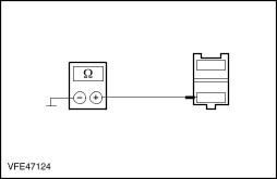
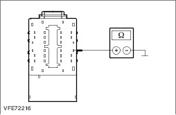
| B24: CHECK THE CENTRAL JUNCTION BOX (CJB) |
| | 1 Ignition switch in position 0. |
| | 2 Disconnect Central junction box (CJB) from connector CBP02B. |
| | 3 Measure the resistance between the central junction box (CJB), connector CBP02B, pin 16, circuit CBP79D (VT/WH), wiring harness side and ground. |
| | Is a resistance of less than 2 Ohm registered? Yes INSTALL a new central junction box (CJB). CHECK the operation of the system. No - Platform truck: LOCATE and RECTIFY the break in the circuit between the central junction box (CJB) and soldered connection S4BP79A with the aid of the Wiring Diagrams. CHECK the operation of the system. - Box van, bus, combi with autolamps and side lights/turn signal lamps: LOCATE and RECTIFY the break in the circuit between the central junction box (CJB) and soldered connection S2BP79, with the aid of the Wiring Diagrams. CHECK the operation of the system. |
| B25: CHECK VOLTAGE SUPPLY OF LEFT-HAND FRONT SIDE LIGHT/TURN SIGNAL LAMP FOR OPEN CIRCUIT |
| | 1 Ignition switch in position 0. |
| | 2 Disconnect Left-hand front side light/turn signal lamp. - Box van, bus, combi: from connector CLS15A
- Platform truck: from connector CLS25
|
| | 3 SWITCH ON the side lights (parking lights). |
| | 4 Measure the voltage between the left-hand front side light/turn signal lamp: - Box van, bus, combi: connector CLS15A, pin 3, circuit CBP76G (BU/BN), wiring harness side, and ground.
- Platform truck: connector CLS25, pin 3, circuit CBP76G (BU/BN), wiring harness side, and ground.
|
| | Is battery voltage measured? Yes No LOCATE and RECTIFY the break in the circuit between soldered connection S1BP76 and the left-hand front side light/turn signal lamp with the aid of the Wiring Diagrams. CHECK the operation of the system. |
| B26: CHECK GROUND CONNECTION TO LEFT-HAND FRONT SIDE LIGHT/TURN SIGNAL LAMP FOR OPEN CIRCUIT |
| | 1 SWITCH OFF the side lights (parking lights). |
| | 2 Measure the resistance between the left-hand front side light/turn signal lamp: - Box van, bus, combi: connector CLS15A, pin 2, circuit A_GD129S (BK/YE), wiring harness side, and ground.
- Platform truck: connector CLS25, pin 2, circuit A_GD129S (BK/YE), wiring harness side, and ground.
|
| | Is a resistance of less than 2 Ohm registered? Yes CHECK and if necessary INSTALL a new left-hand front side light/turn signal lamp. CHECK the operation of the system. No - Box van, bus, combi: LOCATE and RECTIFY the break in the circuit between the left-hand front side light/turn signal lamp and soldered connection S1D129A with the aid of the Wiring Diagrams. CHECK the operation of the system. - Platform truck: LOCATE and RECTIFY the break in the circuit between the left-hand front side light/turn signal lamp and soldered connection S2D129A with the aid of the Wiring Diagrams. CHECK the operation of the system. |
| B27: CHECK VOLTAGE SUPPLY TO LEFT-HAND FRONT CLEARANCE LAMP FOR OPEN CIRCUIT |
| | 1 Ignition switch in position 0. |
| | 2 Disconnect Left-hand front clearance lamp from connector CLS13. |
| | 3 SWITCH ON the side lights (parking lights). |
| | 4 Measure the voltage between the left-hand front clearance lamp, connector CLS13, pin 1, circuit CBP76H (BU/BN), wiring harness side, and ground. |
| | Is battery voltage measured? Yes No LOCATE and RECTIFY the break in the circuit between soldered connection S2BP76 and the left-hand front clearance lamp with the aid of the Wiring Diagrams. CHECK the operation of the system. |
| B28: CHECK GROUND CONNECTION TO LEFT-HAND FRONT CLEARANCE LAMP FOR OPEN CIRCUIT |
| | 1 SWITCH OFF the side lights (parking lights). |
| | 2 Measure the resistance between the left-hand front clearance lamp, connector CLS23, pin 2, circuit A_GD133H (BK), wiring harness side, and ground. |
| | Is a resistance of less than 2 Ohm registered? Yes CHECK and if necessary INSTALL a new left-hand front clearance lamp. CHECK the operation of the system. No LOCATE and RECTIFY the break in the circuit between the left-hand front clearance lamp and soldered connection S2D113C with the aid of the Wiring Diagrams. CHECK the operation of the system. |
| B29: CHECK VOLTAGE SUPPLY OF RIGHT-HAND FRONT SIDE LIGHT/TURN SIGNAL LAMP FOR OPEN CIRCUIT |
| | 1 Ignition switch in position 0. |
| | 2 Disconnect Right-hand front side light/turn signal lamp. - Box van, bus, combi: from connector CLS14B
- Platform truck: from connector CLS21
|
| | 3 SWITCH ON the side lights (parking lights). |
| | 4 Measure the voltage between the left-hand front side light/turn signal lamp: - Box van, bus, combi: connector CLS14B, pin 3, circuit CBP75G (YE/GY), wiring harness side, and ground.
- Platform truck: connector CLS21, pin 3, circuit CBP75G (YE/GY), wiring harness side, and ground.
|
| | Is battery voltage measured? Yes No LOCATE and RECTIFY the break in the circuit between soldered connection S1BP75 and the right-hand front side light/turn signal lamp with the aid of the Wiring Diagrams. CHECK the operation of the system. |
| B30: CHECK GROUND CONNECTION TO RIGHT-HAND FRONT SIDE LIGHT/TURN SIGNAL LAMP FOR OPEN CIRCUIT |
| | 1 SWITCH OFF the side lights (parking lights). |
| | 2 Measure the resistance between the right-hand front side light/turn signal lamp: - Box van, bus, combi: connector CLS14B, pin 2, circuit A_GD131S (BK/GY), wiring harness side, and ground.
- Platform truck: connector CLS21, pin 2, circuit A_GD131S (BK/RD), wiring harness side, and ground.
|
| | Is a resistance of less than 2 Ohm registered? Yes CHECK and if necessary INSTALL a new right-hand front side light/turn signal lamp. CHECK the operation of the system. No LOCATE and RECTIFY the break in the circuit between the right-hand front side light/turn signal lamp and soldered connection S1D131B with the aid of the Wiring Diagrams. CHECK the operation of the system. |
| B31: CHECK VOLTAGE SUPPLY TO RIGHT-HAND FRONT CLEARANCE LAMP FOR OPEN CIRCUIT |
| | 1 Ignition switch in position 0. |
| | 2 Disconnect Right-hand front clearance lamp from connector CLS14. |
| | 3 SWITCH ON the side lights (parking lights). |
| | 4 Measure the voltage between the right-hand front clearance lamp, connector CLS14, pin 1, circuit CBP75L (YE/GY), wiring harness side, and ground. |
| | Is battery voltage measured? Yes No LOCATE and RECTIFY the break in the circuit between soldered connection S2BP75 and the right-hand front clearance lamp with the aid of the Wiring Diagrams. CHECK the operation of the system. |
| B32: CHECK GROUND CONNECTION TO RIGHT-HAND FRONT CLEARANCE LAMP FOR OPEN CIRCUIT |
| | 1 SWITCH OFF the side lights (parking lights). |
| | 2 Measure the resistance between the right-hand front clearance lamp, connector CLS14, pin 2, circuit A_GD138H (BK/WH), wiring harness side, and ground. |
| | Is a resistance of less than 2 Ohm registered? Yes CHECK and if necessary INSTALL a new right-hand front clearance lamp. CHECK the operation of the system. No LOCATE and RECTIFY the break in the circuit between the right-hand front clearance lamp and soldered connection S9D138A with the aid of the Wiring Diagrams. CHECK the operation of the system. |
| B33: CHECK FUSE F75 (7.5 A) (CJB). |
| | 1 Disconnect Fuse F75 (7.5 A) (CJB). |
| | 2 CHECK Fuse F75 (7.5 A) (CJB). |
| | Is the fuse OK? Yes No INSTALL a new fuse F75 (7.5 A) (CJB) and CHECK the operation of the system. If the fuse blows again, LOCATE and RECTIFY the short to ground with the aid of the Wiring Diagrams. CHECK the operation of the system. |
| B34: CHECK THE VOLTAGE SUPPLY TO FUSE F75 (7.5 A) (CJB) FOR OPEN CIRCUIT |
| | 1 Connect Fuse F75 (7.5 A) (CJB). |
| | 2 Measure the voltage between fuse F75 (7.5 A) (CJB) and ground. |
| | Is battery voltage measured? Yes No LOCATE and RECTIFY the break in the voltage supply of fuse F75 (7.5 A) (CJB) with the aid of the Wiring Diagrams. If necessary INSTALL a new central junction box (CJB). CHECK the operation of the system. |
| B35: CHECK THE CENTRAL JUNCTION BOX (CJB) |
| | 1 Ignition switch in position 0. |
| | 2 Disconnect Central junction box (CJB) from connector CBP02B. |
| | 3 Measure the resistance between the central junction box (CJB), connector CBP02B, pin 20, circuit CBP75A (YE/GY), wiring harness side and ground. |
| | Is a resistance of less than 2 Ohm registered? Yes INSTALL a new central junction box (CJB). CHECK the operation of the system. No LOCATE and RECTIFY the break in the circuit between the central junction box (CJB) and soldered connection S2BP75 with the aid of the Wiring Diagrams. CHECK the operation of the system. |
| B36: CHECK FUSE F76 (7.5 A) (CJB). |
| | 1 Disconnect Fuse F76 (7.5 A) (CJB). |
| | 2 CHECK Fuse F76 (7.5 A) (CJB). |
| | Is the fuse OK? Yes No INSTALL a new fuse F76 (7.5 A) (CJB) and CHECK the operation of the system. If the fuse blows again, LOCATE and RECTIFY the short to ground with the aid of the Wiring Diagrams. CHECK the operation of the system. |
| B37: CHECK THE VOLTAGE SUPPLY TO FUSE F76 (7.5 A) (CJB) FOR OPEN CIRCUIT |
| | 1 Connect Fuse F76 (7.5 A) (CJB). |
| | 2 Measure the voltage between fuse F76 (7.5 A) (CJB) and ground. |
| | Is battery voltage measured? Yes No LOCATE and RECTIFY the break in the voltage supply of fuse F76 (7.5 A) (CJB) with the aid of the Wiring Diagrams. If necessary INSTALL a new central junction box (CJB). CHECK the operation of the system. |
| B38: CHECK THE CENTRAL JUNCTION BOX (CJB) |
| | 1 Ignition switch in position 0. |
| | 2 Disconnect Central junction box (CJB) from connector CBP02B. |
| | 3 Measure the resistance between the central junction box (CJB), connector CBP02B, pin 28, circuit CBP76A (BU/BN), wiring harness side and ground. |
| | Is a resistance of less than 2 Ohm registered? Yes INSTALL a new central junction box (CJB). CHECK the operation of the system. No LOCATE and RECTIFY the break in the circuit between the central junction box (CJB) and soldered connection S2BP76 with the aid of the Wiring Diagrams. CHECK the operation of the system. |
| B39: CHECK FUSE F75 (7.5 A) (CJB). |
| | 1 Disconnect Fuse F75 (7.5 A) (CJB). |
| | 2 CHECK Fuse F75 (7.5 A) (CJB). |
| | Is the fuse OK? Yes No INSTALL a new fuse F75 (7.5 A) (CJB) and CHECK the operation of the system. If the fuse blows again, LOCATE and RECTIFY the short to ground with the aid of the Wiring Diagrams. CHECK the operation of the system. |
| B40: CHECK THE VOLTAGE SUPPLY TO FUSE F75 (7.5 A) (CJB) FOR OPEN CIRCUIT |
| | 1 Connect Fuse F75 (7.5 A) (CJB). |
| | 2 Measure the voltage between fuse F75 (7.5 A) (CJB) and ground. |
| | Is battery voltage measured? Yes No LOCATE and RECTIFY the break in the voltage supply of fuse F75 (7.5 A) (CJB) with the aid of the Wiring Diagrams. If necessary INSTALL a new central junction box (CJB). CHECK the operation of the system. |
| B41: CHECK THE CENTRAL JUNCTION BOX (CJB) |
| | 1 Ignition switch in position 0. |
| | 2 Disconnect Central junction box (CJB) from connector CBP02B. |
| | 3 Measure the resistance between the central junction box (CJB), connector CBP02B, pin 20, circuit CBP75(A) (YE/GY), wiring harness side and ground. |
| | Is a resistance of less than 2 Ohm registered? Yes INSTALL a new central junction box (CJB). CHECK the operation of the system. No LOCATE and RECTIFY the break in the circuit between the central junction box (CJB) and soldered connection S2BP75 with the aid of the Wiring Diagrams. CHECK the operation of the system. |