| PINPOINT TEST C : ONE OR MORE TURN SIGNAL LAMPS INOPERATIVE |
| TEST CONDITIONS | DETAILS/RESULTS/ACTIONS |
| C1: DETERMINE THE INOPERATIVE TURN SIGNAL LAMP(S) |
| | 1 Ignition switch in position II. |
| | 2 CHECK the turn signal lamps after each action. |
| | 3 DETERMINE which turn signal lamp is inoperative. |
| | 4 SWITCH ON the left-hand turn signal. |
| | 5 SWITCH ON the right-hand turn signal. |
| | Is a turn signal lamp on the left-hand side inoperative? Yes - All turn signal lamps on left-hand side inoperative: GO to C2. - Only the front left-hand turn signal lamp is inoperative: GO to C4. - Only the left-hand turn side repeater lamp is inoperative: GO to C6. - Only the left-hand parking light/left-hand turn side repeater lamp is inoperative: GO to C8. - The front and side (side)/turn signal lamps on the left-hand side are inoperative: GO to C10. - Only the rear left turn signal lamp is inoperative; box van, bus, combi only: GO to C12. - Only the rear left-hand turn signal lamp is inoperative, platform truck only: GO to C14. No - All turn signal lamps on right-hand side inoperative: GO to C2. - Only the front right turn signal lamp is inoperative; box van, bus, combi only: GO to C17. - Only the front right turn signal lamp is inoperative, platform truck only: GO to C19. - Only the side turn signal lamp on the right-hand side is inoperative: GO to C21. - Only the right-hand side light/turn signal lamp is inoperative: GO to C23. - The front and side (side)/turn signal lamps on the right-hand side are inoperative; box van, bus and combi only: GO to C25. - The front and side (side)/turn signal lamps on the right-hand side are inoperative; platform truck only: GO to C27. - Only the rear right turn signal lamp is inoperative; box van, bus, combi only: GO to C29. - Only the rear right turn signal lamp is inoperative, platform truck only: GO to C32. - Both rear turn signal lamps are inoperative, platform truck only: GO to C41. - Both rear turn signal lamps are inoperative; box van, bus, combi with trailer socket only: GO to C42. |
| C2: RULE OUT THE STEERING COLUMN MULTIFUNCTION SWITCH AS A CAUSE FOR THE CONCERN |
| | 1 Ignition switch in position 0. |
| | 2 Disconnect Steering column multifunction switch from connector CLS34. |
| | 3 Left-hand turn signal lamps inoperative: Connect a fused (5 A) jumper lead at steering column multifunction switch, connector CLS34, between pin 6, circuit CLS39A (VT/WH) wiring harness side and pin 10, circuit B_GD115D (BK/GY), wiring harness side: |
| | 4 Right-hand turn signal lamps inoperative: Connect a fused (5 A) jumper lead at the steering column multifunction switch, connector CLS34, between pin 7, circuit CLS41A (GY/YE) wiring harness side and pin 10, circuit B_GD115D (BK/GY), wiring harness side: |
| | 5 Ignition switch in position II. |
| | 6 CHECK the turn signal lamps. |
| | Do all the turn signal lamps flash on the affected side? Yes RENEW steering column multifunction switch. CHECK the operation of the system. No |
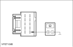
| C3: CHECK THE CONTROL CIRCUIT BETWEEN THE STEERING COLUMN MULTIFUNCTION SWITCH AND THE GEM (GENERIC ELECTRONIC MODULE) FOR OPEN CIRCUIT |
| | 1 Ignition switch in position 0. |
| | 2 Disconnect Generic Electronic Module (GEM). - Box van / Bus / Combi: from connector C2BP02F
- Platform truck: from connector CBP02F
|
| | 3 Left-hand turn signal lamps inoperative: Measure the resistance between the steering column multifunction switch, connector CLS34, pin 6, circuit CLS39A (VT/WH), wiring harness side and the generic electronic module (GEM). - Box van / Bus / Combi: Connector C2BP02F, pin 9, circuit CLS39A (VT/WH), wiring harness side.
- Platform truck: Connector CBP02F, pin 9, circuit CLS39A (VT/WH), wiring harness side.
|
| | 4 Right-hand turn signal lamps inoperative: Measure the resistance between the steering column multifunction switch, connector CLS34, pin 7, circuit CLS41A (GY/YE), wiring harness side and the generic electronic module (GEM). - Box van / Bus / Combi: Connector C2BP02F, pin 10, circuit CLS41A (GY/YE), wiring harness side.
- Platform truck: Connector CBP02F, pin 10, circuit CLS41A (GY/YE), wiring harness side.
|
| | Is a resistance of less than 2 Ohms registered? Yes RENEW the generic electronic module (GEM). CHECK the operation of the system. No LOCATE and REPAIR open circuit between steering column multifunction switch and generic electronic module (GEM) using the Wiring Diagrams. CHECK the operation of the system. |
| C4: CHECK THE VOLTAGE SUPPLY OF THE LEFT-HAND HEADLAMP FOR OPEN CIRCUIT |
| | 1 Ignition switch in position 0. |
| | 2 Disconnect Left-hand headlamp from. - Box van, bus, combi, without trailer socket, with side parking lamp/turn signal lamp: Connector C1LF08
- All other vehicles: Connector CLF08
|
| | 3 Ignition switch in position II. |
| | 4 SWITCH ON the left-hand turn signal. |
| | 5 At the left-hand headlamp, measure the voltage between: - Box van, bus, combi, without trailer socket, with side parking lamp/turn signal lamp: Connector C1LF08, pin 1, circuit CLS21E (BU/GN), wiring harness side and ground.
- Platform truck without side parking lamp/turn signal lamp: Connector CLF08, pin 1, circuit CLS21B (BU/GN), wiring harness side and ground.
- All other vehicles: Connector CLF08, pin 1, circuit CLS21E (BU/GN), wiring harness side and ground.
|
| | Is fluctuating battery voltage measured? Yes No LOCATE and REPAIR break in circuit(s) between soldered connection S2LS21 and headlamp using the Wiring Diagrams. CHECK the operation of the system. |
| C5: CHECK GROUND SUPPLY OF LEFT-HAND HEADLAMP FOR OPEN CIRCUIT |
| | 1 Ignition switch in position 0. |
| | 2 Measure the resistance at the left-hand headlamp between: - Box van, bus, combi, without trailer socket, with side parking lamp/turn signal lamp: Connector C1LF08, pin 4, circuit A_GD129T (BK/YE), wiring harness side and ground.
- All other vehicles: Connector CLF08, pin 4, circuit A_GD129E (BK/YE), wiring harness side and ground.
|
| | Is a resistance of less than 2 Ohms registered? Yes CHECK and if necessary RENEW the headlamp. CHECK the operation of the system. No - Box van, bus, combi: LOCATE and RECTIFY the break in the circuit between the headlamp and soldered connection S1D129A using the Wiring Diagrams. CHECK the operation of the system. - Chassis cab vehicle: LOCATE and RECTIFY the break in the circuit between the headlamp and soldered connection S2D129A using the Wiring Diagrams. CHECK the operation of the system. |
| C6: CHECK THE VOLTAGE SUPPLY TO THE LEFT-HAND TURN SIGNAL LAMP (SIDE) FOR OPEN CIRCUIT |
| | 1 Ignition switch in position 0. |
| | 2 Disconnect left-hand turn signal lamp (side) from connector CLS25. |
| | 3 Ignition switch in position II. |
| | 4 SWITCH ON the left-hand turn signal. |
| | 5 Measure the voltage between the left-hand turn signal lamp (side), connector CLS25, pin 1, circuit CLS21C (BU/GN), wiring harness side and ground. |
| | Is fluctuating battery voltage measured? Yes No LOCATE and REPAIR break in circuit(s) between soldered connection S2LS21 and turn signal lamp (side) using the Wiring Diagrams. CHECK the operation of the system. |
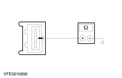
| C7: CHECK THE GROUND CONNECTION OF THE LEFT-HAND (SIDE) TURN SIGNAL LAMP FOR OPEN CIRCUIT |
| | 1 Ignition switch in position 0. |
| | 2 Measure the resistance between the left-hand turn signal lamp (side), connector CLS25, pin 2, circuit A_GD129C (BK/YE), wiring harness side and ground. |
| | Is a resistance of less than 2 Ohms registered? Yes CHECK and if necessary RENEW the turn signal side lamp. CHECK the operation of the system. No LOCATE and RECTIFY the break in the circuit between the (side) turn signal lamp and soldered connection S2D129A using the Wiring Diagrams. CHECK the operation of the system. |
| C8: CHECK THE VOLTAGE SUPPLY TO THE LEFT-HAND SIDE PARKING LAMP/TURN SIGNAL LAMP FOR OPEN CIRCUIT |
| | 1 Ignition switch in position 0. |
| | 2 Disconnect Left-hand side parking lamp/turn signal lamp from . - Box van / bus / combi, without a trailer socket: Connector C1LS15A
- Chassis cab vehicle: connector CLS25
- All other vehicles: connector CLS15A
|
| | 3 Ignition switch in position II. |
| | 4 SWITCH ON the left-hand turn signal. |
| | 5 Measure the voltage at the left-hand side parking lamp/turn signal lamp between: - Box van / bus / combi, without a trailer socket: Connector C1LS15A, pin 1, circuit CLS21D (BU/GN), wiring harness side and ground.
- Chassis cab vehicle: Connector CLS25, pin 1, circuit CLS21D (BU/GN), wiring harness side and ground.
- All other vehicles: Connector CLS15A, pin 1, circuit CLS21D (BU/GN), wiring harness side and ground.
|
| | Is fluctuating battery voltage measured? Yes No LOCATE and REPAIR break in circuit(s) between soldered connection S2LS21 and side parking lamp/turn signal lamp using the Wiring Diagrams. CHECK operation of system. |
| C9: CHECK THE GROUND CONNECTION OF THE LEFT-HAND SIDE PARKING LAMP/TURN SIGNAL LAMP FOR OPEN CIRCUIT |
| | 1 Ignition switch in position 0. |
| | 2 Measure resistance between left-hand side parking lamp/turn signal lamp, - Box van / bus / combi, without a trailer socket: Connector C1LS15A, pin 2, circuit A_GD129S (BK/YE), wiring harness side and ground.
- Chassis cab vehicle: Connector CLS25, pin 2, circuit A_GD129S (BK/YE), wiring harness side and ground.
- All other vehicles: Connector CLS15A, pin 2, circuit A_GD129S (BK/YE), wiring harness side and ground.
|
| | Is a resistance of less than 2 Ohms registered? Yes CHECK and if necessary RENEW the side parking lamp/turn signal lamp. CHECK the operation of the system. No - Box van, bus, combi: LOCATE and RECTIFY the break in the circuit between the side parking lamp/turn signal lamp and soldered connection S1D129A using the Wiring Diagrams. CHECK the operation of the system. - Chassis cab vehicle: LOCATE and RECTIFY the break in the circuit between the side parking lamp/turn signal lamp and soldered connection S2D129A using the Wiring Diagrams. CHECK the operation of the system. |
| C10: CHECK THE COMMON GROUND OF THE FRONT LEFT-HAND TURN SIGNAL LAMPS FOR OPEN CIRCUIT |
| | 1 Ignition switch in position 0. |
| | 2 Disconnect Left-hand headlamp from. - Box van, bus, combi, without trailer socket, with side parking lamp/turn signal lamp: Connector C1LF08
- All other vehicles: Connector CLF08
|
| | 3 Ignition switch in position II. |
| | 4 SWITCH ON the left-hand turn signal. |
| | 5 At the left-hand headlamp, measure the voltage between: - Box van, bus, combi, without trailer socket, with side parking lamp/turn signal lamp: Connector C1LF08, pin 1, circuit CLS21E (BU/GN), wiring harness side and ground.
- Platform truck without side parking lamp/turn signal lamp: Connector CLF08, pin 1, circuit CLS21B (BU/GN), wiring harness side and ground.
- All other vehicles: Connector CLF08, pin 1, circuit CLS21E (BU/GN), wiring harness side and ground.
|
| | Is fluctuating battery voltage measured? Yes - Box van / Bus / Combi: LOCATE and RECTIFY break in circuits between soldered connection S1D129A and ground connection G29 with the aid of the Wiring Diagrams. CHECK the operation of the system. - Platform truck: LOCATE and RECTIFY break in circuits between soldered connection S2D129A and ground connection G29 with the aid of the Wiring Diagrams. CHECK the operation of the system. No |
| C11: CHECK THE VOLTAGE SUPPLY TO THE FRONT LEFT-HAND TURN SIGNAL LAMPS FOR OPEN CIRCUIT |
| | 1 Ignition switch in position 0. |
| | 2 Connect left-hand headlamp. - Box van, bus, combi, without trailer socket, with side parking lamp/turn signal lamp: to connector C1LF08
- All other vehicles: to connector CLF08
|
| | 3 Disconnect Generic Electronic Module (GEM). |
| | 4 Measure the resistance between the generic electronic module (GEM): - Box van / Bus / Combi: Connector C2BP02D between pin 29, circuit CLS21A (BU/GN), wiring harness side and ground.
- Platform truck: Connector CBP02D between pin 29, circuit CLS21A (BU/GN), wiring harness side and ground.
|
| | Is a resistance of more than 10,000 ohms measured? Yes LOCATE and RECTIFY the break in the circuits between generic electronic module (GEM) and soldered connection S2LS21 using the Wiring Diagrams. CHECK the operation of the system. No RENEW the generic electronic module (GEM). CHECK the operation of the system. |
| C12: CHECK THE VOLTAGE SUPPLY TO THE LEFT-HAND REAR LAMP ASSEMBLY FOR OPEN CIRCUIT (BOX VAN, BUS, COMBI) |
| | 1 Ignition switch in position 0. |
| | 2 Disconnect Left-hand rear lamp assembly from connector CLS22. |
| | 3 Ignition switch in position II. |
| | 4 SWITCH ON the left-hand turn signal. |
| | 5 Measure the voltage between the left-hand rear lamp assembly: - Vehicles without trailer socket: connector CLS22, pin 2, circuit CLS23B (GY/OG), wiring harness side and ground.
- Vehicles with trailer socket: connector CLS22, pin 2, circuit B_CLS23C (GY/OG), wiring harness side and ground.
|
| | Is fluctuating battery voltage measured? Yes No - Vehicles without trailer socket: GO to C16. |
| C13: CHECK THE GROUND SUPPLY OF THE LEFT-HAND REAR LAMP ASSEMBLY FOR OPEN CIRCUIT (BOX VAN, BUS, COMBI) |
| | 1 Ignition switch in position 0. |
| | 2 Measure the resistance between the left-hand rear lamp assembly: - Vehicles without trailer socket: Connector CLS22, pin 5, circuit A_GD149C (BK/GY), wiring harness side and ground.
- Vehicles with trailer socket: Connector CLS22, pin 5, circuit A_GD149N (BK/GY), wiring harness side and ground.
|
| | Is a resistance of less than 2 Ohms registered? Yes CHECK and if necessary INSTALL A NEW rear lamp assembly. CHECK the operation of the system. No - Vehicles without trailer socket: LOCATE and RECTIFY the break in the circuit between rear lamp assembly and soldered connection S4D149B using the Wiring Diagrams. CHECK the operation of the system. - Vehicles with a trailer socket: LOCATE and RECTIFY the break in the circuit between the rear lamp assembly and soldered connection S4D149A with the aid of the Wiring Diagrams. CHECK the operation of the system. |
| C14: CHECK THE VOLTAGE SUPPLY TO THE LEFT-HAND REAR LAMP ASSEMBLY FOR OPEN CIRCUIT (PLATFORM TRUCK) |
| | 1 Ignition switch in position 0. |
| | 2 Disconnect left-hand rear lamp assembly:. - Vehicles with trailer socket, with side parking lamp/turn signal lamp: from connector CLS04
- All other vehicles: from connector CLS35
|
| | 3 Ignition switch in position II. |
| | 4 SWITCH ON the left-hand turn signal. |
| | 5 Measure the voltage between the left-hand rear lamp assembly: - Vehicles without trailer socket: connector CLS35, pin 4, circuit CLS23H (GY/OG), wiring harness side and ground.
- Vehicles with trailer socket: connector CLS35 (CLS04), pin 4, circuit B_CLS23C (GY/OG), wiring harness side and ground.
|
| | Is fluctuating battery voltage measured? Yes No - Vehicles without trailer socket: GO to C16. |
| C15: CHECK THE GROUND SUPPLY OFTHE LEFT-HAND REAR LAMP ASSEMBLY FOR OPEN CIRCUIT (PLATFORM TRUCK) |
| | 1 Ignition switch in position 0. |
| | 2 Measure the resistance between the left-hand rear lamp assembly, connector CLS35 (CLS04), pin 1, circuit B_GD129U (BK/YE), wiring harness side and ground. |
| | Is a resistance of less than 2 Ohms registered? Yes CHECK and if necessary INSTALL A NEW rear lamp assembly. CHECK the operation of the system. No LOCATE and RECTIFY the break in the circuit between the rear lamp assembly and soldered connection S4D129G with the aid of the Wiring Diagrams. CHECK operation of system. |
| C16: CHECK THE VOLTAGE SUPPLY TO THE LEFT-HAND REAR LAMP ASSEMBLY FOR OPEN CIRCUIT |
| | 1 Ignition switch in position 0. |
| | 2 Connect left-hand rear lamp assembly:. - Box van / Bus / Combi: to connector CLS22
- Platform truck: to connector CLS35
|
| | 3 Disconnect Generic Electronic Module (GEM) from. - Box van / Bus / Combi: Connector C2BP02D
- Platform truck: Connector CBP02D
|
| | 4 Measure the resistance between the generic electronic module (GEM): - Box van / Bus / Combi: connector C2BP02D, pin 30, circuit CLS23A (GY/OG), wiring harness side and ground.
- Platform truck: connector CBP02D, pin 30, circuit CLS23A (GY/OG), wiring harness side and ground.
|
| | Is a resistance of more than 10,000 ohms measured? Yes LOCATE and RECTIFY the break in the circuits between the generic electronic module (GEM) and the rear lamp assembly using the Wiring Diagrams. CHECK the operation of the system. No RENEW the generic electronic module (GEM). CHECK the operation of the system. |
| C17: CHECK THE VOLTAGE SUPPLY TO THE FRONT RIGHT-HAND TURN SIGNAL LAMP FOR OPEN CIRCUIT (BOX VAN, BUS, COMBI) |
| | 1 Ignition switch in position 0. |
| | 2 Disconnect Right front turn signal indicator lamp. - Vehicles without trailer socket: from connector C1LF09
- Vehicles with trailer socket: from connector CLF09
|
| | 3 Ignition switch in position II. |
| | 4 SWITCH ON the right-hand turn signal. |
| | 5 CHECK the turn signal lamps. |
| | 6 At the right-hand headlamp, measure the voltage between: - Vehicles without trailer socket: Connector C1LF09, pin 1, circuit CLS25D (YE/VT), wiring harness side and ground.
- Vehicles with trailer socket: Connector CLF09, pin 1, circuit CLS25D (YE/VT), wiring harness side and ground.
|
| | Is fluctuating battery voltage measured? Yes No LOCATE and REPAIR break in circuit(s) between soldered connection S2LS25 and headlamp using the Wiring Diagrams. CHECK the operation of the system. |
| C18: CHECK THE GROUND SUPPLY OF THE RIGHT-HAND HEADLAMP FOR OPEN CIRCUIT (BOX VAN, BUS, COMBI) |
| | 1 Ignition switch in position 0. |
| | 2 Measure the resistance between the right-hand headlamp: - Vehicles without trailer socket: Connector C1LF09, pin 4, circuit A_GD131V (BK/GY), wiring harness side and ground.
- Vehicles with trailer socket: Connector CLF09, pin 4, circuit A_GD131(V/Y) (BK/GY), wiring harness side and ground.
|
| | Is a resistance of less than 2 Ohms registered? Yes CHECK and if necessary RENEW the headlamp. CHECK the operation of the system. No LOCATE and RECTIFY the break in the circuit between the headlamp and soldered connection S1D131B using the Wiring Diagrams. CHECK the operation of the system. |
| C19: CHECK THE VOLTAGE SUPPLY TO THE FRONT RIGHT-HAND TURN SIGNAL LAMP FOR OPEN CIRCUIT (PLATFORM TRUCK) |
| | 1 Ignition switch in position 0. |
| | 2 Disconnect Right front turn signal indicator lamp. - Vehicles with trailer socket: from connector C1LF09
- Vehicles without trailer socket: from connector CLF09
|
| | 3 Ignition switch in position II. |
| | 4 SWITCH ON the right-hand turn signal. |
| | 5 CHECK the turn signal lamps. |
| | 6 At the right-hand headlamp, measure the voltage between: - Vehicles without trailer socket, without side parking lamp/turn signal lamp: Connector CLF09, pin 1, circuit CLS25B (YE/VT), wiring harness side and ground.
- Vehicles without trailer socket, with side parking lamp/turn signal lamp: Connector CLF09, pin 1, circuit CLS25E (YE/VT), wiring harness side and ground.
- Vehicles with trailer socket, without side parking lamp/turn signal lamp: Connector C1LF09, pin 1, circuit CLS25B (YE/VT), wiring harness side and ground.
- Vehicles with trailer socket, with side parking lamp/turn signal lamp: Connector C1LF09, pin 1, circuit CLS25E (YE/VT), wiring harness side and ground.
|
| | Is fluctuating battery voltage measured? Yes No LOCATE and REPAIR break in circuit(s) between soldered connection S2LS25 and headlamp using the Wiring Diagrams. CHECK the operation of the system. |
| C20: CHECK THE GROUND CONNECTION TO THE RIGHT-HAND HEADLAMP FOR OPEN CIRCUIT (PLATFORM TRUCK) |
| | 1 Ignition switch in position 0. |
| | 2 Measure the resistance between the right-hand headlamp: - Vehicles without trailer socket: Connector CLF09, pin 4, circuit A_GD131(T/H) (BK/GY), wiring harness side and ground.
- Vehicles with trailer socket: Connector C1LF09, pin 4, circuit A_GD131(T/H) (BK/GY), wiring harness side and ground.
|
| | Is a resistance of less than 2 Ohms registered? Yes CHECK and if necessary RENEW the headlamp. CHECK the operation of the system. No LOCATE and RECTIFY the break in the circuit between the headlamp and soldered connection S1D131B using the Wiring Diagrams. CHECK the operation of the system. |
| C21: CHECK THE VOLTAGE SUPPLY OF THE RIGHT-HAND TURN SIGNAL LAMP (SIDE) FOR OPEN CIRCUIT |
| | 1 Ignition switch in position 0. |
| | 2 Disconnect right-hand turn signal lamp (side) from connector CLS21. |
| | 3 Ignition switch in position II. |
| | 4 SWITCH ON the right-hand turn signal. |
| | 5 Measure the voltage between the right-hand turn signal lamp (side), connector CLS21, pin 1, circuit CLS25C (YE/VT), wiring harness side and ground. |
| | Is fluctuating battery voltage measured? Yes No LOCATE and REPAIR break in circuit(s) between soldered connection S2LS25 and turn signal lamp (side) using the Wiring Diagrams. CHECK the operation of the system. |
| C22: CHECK THE GROUND CONNECTION OF THE RIGHT-HAND (SIDE) TURN SIGNAL LAMP FOR OPEN CIRCUIT |
| | 1 Ignition switch in position 0. |
| | 2 Measure the resistance between the right-hand turn signal lamp (side), connector CLS21, pin 2, circuit A_GD131F (BK/GY), wiring harness side and ground. |
| | Is a resistance of less than 2 Ohms registered? Yes CHECK and if necessary RENEW the turn signal side lamp. CHECK the operation of the system. No LOCATE and RECTIFY the break in the circuit between the (side) turn signal lamp and soldered connection S1D131B using the Wiring Diagrams. CHECK the operation of the system. |
| C23: CHECK THE VOLTAGE SUPPLY TO THE RIGHT-HAND SIDE PARKING LAMP/TURN SIGNAL LAMP FOR OPEN CIRCUIT |
| | 1 Ignition switch in position 0. |
| | 2 Disconnect Right-hand side parking lamp/turn signal lamp. - Box van / Bus / Combi: from connector C1LS14B
- Platform truck: from connector CLS21
|
| | 3 Ignition switch in position II. |
| | 4 SWITCH ON the right-hand turn signal. |
| | 5 Measure the voltage between right-hand side parking lamp/turn signal lamp: - Box van / Bus / Combi: Connector C1LS14B, pin 1, circuit CLS25E (YE/VT), wiring harness side and ground.
- Chassis cab vehicle: Connector CLS21, pin 1, circuit CLS25D (YE/VT), wiring harness side and ground.
|
| | Is fluctuating battery voltage measured? Yes No LOCATE and REPAIR break in circuit(s) between soldered connection S2LS25 and side parking lamp/turn signal lamp using the Wiring Diagrams. CHECK the operation of the system. |
| C24: CHECK THE GROUND CONNECTION OF THE RIGHT-HAND SIDE PARKING LAMP/TURN SIGNAL LAMP FOR OPEN CIRCUIT |
| | 1 Ignition switch in position 0. |
| | 2 Measure resistance between right-hand side parking lamp/turn signal lamp: - Box van / Bus / Combi: Connector C1LS14B, pin 2, circuit A_GD131X (BK/GY), wiring harness side and ground.
- Platform truck: Connector CLS21, pin 2, circuit A_GD131S (BK/GY), wiring harness side and ground.
|
| | Is a resistance of less than 2 Ohms registered? Yes CHECK and if necessary RENEW the side parking lamp/turn signal lamp. CHECK the operation of the system. No LOCATE and REPAIR break in circuit(s) between side parking lamp/turn signal lamp and soldered connection S1D131B using the Wiring Diagrams. CHECK the operation of the system. |
| C25: CHECK THE SHARED GROUND SUPPLY OF THE FRONT RIGHT TURN SIGNAL LAMPS FOR OPEN CIRCUIT (BOX VAN, BUS, COMBI) |
| | 1 Ignition switch in position 0. |
| | 2 Disconnect Right parking lamp (side)/turn signal lamp from connector C1LS14B. |
| | 3 Ignition switch in position II. |
| | 4 SWITCH ON the right-hand turn signal. |
| | 5 Measure the voltage between the right-hand parking lamp/turn signal lamp (side), connector C1LS14B, pin 1, circuit CLS25E (YE/VT), wiring harness side and ground. |
| | Is fluctuating battery voltage measured? Yes LOCATE and RECTIFY break in circuits between soldered connection S1D131B and ground connection G31 with the aid of the Wiring Diagrams. CHECK the operation of the system. No |
| C26: CHECK THE SHARED VOLTAGE SUPPLY TO THE FRONT RIGHT TURN SIGNAL LAMPS FOR OPEN CIRCUIT (BOX VAN, BUS, COMBI) |
| | 1 Ignition switch in position 0. |
| | 2 Connect Right parking lamp (side)/turn signal lamp from connector C1LS14B. |
| | 3 Disconnect Generic electronic module (GEM) from connector C2BP02D. |
| | 4 Measure the resistance between the generic electronic module (GEM), connector C2BP02D, pin 40, circuit CLS25A (YE/VT), wiring harness side and ground. |
| | Is a resistance of more than 10,000 ohms measured? Yes LOCATE and RECTIFY the break in circuit between generic electronic module (GEM) and soldered connection S2LS25 using the Wiring Diagrams. CHECK the operation of the system. No RENEW the generic electronic module (GEM). CHECK the operation of the system. |
| C27: CHECK THE COMMON GROUND OF THE FRONT RIGHT-HAND TURN SIGNAL LAMPS FOR OPEN CIRCUIT (PLATFORM TRUCK) |
| | 1 Ignition switch in position 0. |
| | 2 Disconnect right-hand headlamp. - Vehicles without trailer socket: from connector CLF09
- Vehicles with trailer socket: from connector C1LF09
|
| | 3 Ignition switch in position II. |
| | 4 SWITCH ON the right-hand turn signal. |
| | 5 At the right-hand headlamp, measure the voltage between: - Vehicles without trailer socket, without side parking lamp/turn signal lamp: Connector CLF09, pin 1, circuit CLS25B (YE/VT), wiring harness side and ground.
- Vehicles without trailer socket, with side parking lamp/turn signal lamp: Connector CLF09, pin 1, circuit CLS25E (YE/VT), wiring harness side and ground.
- Vehicles with trailer socket, without side parking lamp/turn signal lamp: Connector C1LF09, circuit CLS25B (YE/VT), wiring harness side and ground.
- Vehicles with trailer socket, with side parking lamp/turn signal lamp: Connector C1LF09, circuit CLS25E (YE/VT), wiring harness side and ground.
|
| | Is fluctuating battery voltage measured? Yes LOCATE and RECTIFY break in circuits between soldered connection S1D131B and ground connection G31 with the aid of the Wiring Diagrams. CHECK the operation of the system. No |
| C28: CHECK THE COMMON VOLTAGE SUPPLY TO THE FRONT RIGHT-HAND TURN SIGNAL LAMPS FOR OPEN CIRCUIT (PLATFORM TRUCK) |
| | 1 Ignition switch in position 0. |
| | 2 Connect right-hand headlamp. - Vehicles without trailer socket: to connector CLF09
- Vehicles with trailer socket: to connector C1LF09
|
| | 3 Disconnect Generic electronic module (GEM) from connector CBP02D. |
| | 4 Measure the resistance between the generic electronic module (GEM), connector CBP02D, pin 40, circuit CLS25A (YE/VT), wiring harness side and ground. |
| | Is a resistance of more than 10,000 ohms measured? Yes LOCATE and RECTIFY the break in circuit between generic electronic module (GEM) and soldered connection S2LS25 using the Wiring Diagrams. CHECK the operation of the system. No RENEW the generic electronic module (GEM). CHECK the operation of the system. |
| C29: CHECK THE VOLTAGE SUPPLY TO THE RIGHT-HAND REAR LAMP ASSEMBLY FOR OPEN CIRCUIT (BOX VAN, BUS, COMBI) |
| | 1 Ignition switch in position 0. |
| | 2 Disconnect Right-hand rear lamp assembly from connector CLS26. |
| | 3 Ignition switch in position II. |
| | 4 SWITCH ON the right-hand turn signal. |
| | 5 Measure voltage between right-hand rear lamp assembly, connector CLS26: - Vehicles without trailer socket: pin 2, circuit CLS27B (GN/OG), wiring harness side and ground.
- Vehicles with trailer socket: pin 2, circuit B_CLS27C (GN/OG), wiring harness side and ground.
|
| | Is fluctuating battery voltage measured? Yes No - Vehicles without trailer socket: GO to C30. |
| C30: CHECK THE VOLTAGE SUPPLY TO THE RIGHT-HAND REAR LAMP ASSEMBLY FOR OPEN CIRCUIT (BOX VAN, BUS, COMBI) |
| | 1 Ignition switch in position 0. |
| | 2 Disconnect Generic electronic module (GEM) from connector C2BP02D. |
| | 3 Measure the resistance between the generic electronic module (GEM), connector C2BP02D, pin 39, circuit CLS27A (GN/OG), wiring harness side and the rear right lamp assembly, connector CLS26, pin 2, circuit CLS27B (GN/OG), wiring harness side. |
| | Is a resistance of less than 2 Ohms registered? Yes RENEW the generic electronic module (GEM). CHECK the operation of the system. No LOCATE and RECTIFY the break in the circuits between the generic electronic module (GEM) and the rear lamp assembly using the Wiring Diagrams. CHECK the operation of the system. |
| C31: CHECK THE GROUND SUPPLY OF THE RIGHT-HAND REAR LAMP ASSEMBLY FOR OPEN CIRCUIT (BOX VAN, BUS, COMBI) |
| | 1 Ignition switch in position 0. |
| | 2 Measure the resistance between the right-hand rear lamp assembly, connector CLS26: - Vehicles without trailer socket: pin 5, circuit A_GD151H (BK/GN), wiring harness side and ground.
- Vehicles with trailer socket: pin 5, circuit A_GD151AB (BK/GN), wiring harness side and ground.
|
| | Is a resistance of less than 2 Ohms registered? Yes CHECK and if necessary INSTALL A NEW rear lamp assembly. CHECK the operation of the system. No LOCATE and RECTIFY the break in the circuit between the rear lamp assembly and ground connection G51 using the Wiring Diagrams. CHECK the operation of the system. |
| C32: CHECK THE VOLTAGE SUPPLY TO THE RIGHT-HAND REAR LAMP ASSEMBLY FOR OPEN CIRCUIT (PLATFORM TRUCK) |
| | 1 Ignition switch in position 0. |
| | 2 Disconnect right-hand rear lamp assembly. - Vehicles with trailer socket, with (side) parking lamp/turn signal lamp: from connector CLS26
- All other vehicles: connector CLS36
|
| | 3 Ignition switch in position II. |
| | 4 SWITCH ON the right-hand turn signal. |
| | 5 Measure the voltage between the right-hand rear lamp assembly: - Vehicles without trailer socket: connector CLS36, pin 4, circuit CLS27H (GN/OG), wiring harness side and ground.
- Vehicles with trailer socket: connector CLS36, pin 4, circuit B_CLS27C (GN/OG), wiring harness side and ground.
|
| | Is fluctuating battery voltage measured? Yes No - Vehicles without trailer socket: GO to C33. |
| C33: CHECK THE VOLTAGE SUPPLY TO THE RIGHT-HAND REAR LAMP ASSEMBLY FOR OPEN CIRCUIT (PLATFORM TRUCK) |
| | 1 Ignition switch in position 0. |
| | 2 Disconnect Generic electronic module (GEM) from connector CBP02D. |
| | 3 Measure the resistance between the generic electronic module (GEM), connector CBP02D, pin 39, circuit CLS27A (GN/OG), wiring harness side and the rear right lamp assembly, connector CLS36, pin 4, circuit CLS27H (GN/OG), wiring harness side. |
| | Is a resistance of less than 2 Ohms registered? Yes RENEW the generic electronic module (GEM). CHECK the operation of the system. No LOCATE and RECTIFY the break in the circuits between the generic electronic module (GEM) and the rear lamp assembly using the Wiring Diagrams. CHECK the operation of the system. |
| C34: CHECK THE GROUND SUPPLY OF THE RIGHT-HAND REAR LAMP ASSEMBLY FOR OPEN CIRCUIT (PLATFORM TRUCK) |
| | 1 Ignition switch in position 0. |
| | 2 Measure the resistance between the right-hand rear lamp assembly, connector CLS36, pin 1, circuit B_GD129V (BK/YE), wiring harness side and ground. |
| | Is a resistance of less than 2 Ohms registered? Yes CHECK and if necessary INSTALL A NEW rear lamp assembly. CHECK the operation of the system. No LOCATE and RECTIFY the break in the circuit between the rear lamp assembly and soldered connection S4D129G with the aid of the Wiring Diagrams. CHECK the operation of the system. |
| C35: ELIMINATE THE TRAILER CONTROL UNIT AS A POSSIBLE CAUSE FOR THE CONCERN (BOX VAN, BUS, COMBI) |
| | 1 Ignition switch in position 0. |
| | 2 Disconnect Trailer control unit from connector CAT18 (1506). |
| | 3 Ignition switch in position II. |
| | 4 SWITCH ON the hazard warning lamps. |
| | 5 Left-hand turn signal lamp: Measure the voltage between the trailer control unit, connector CAT18 (1506), pin 2, circuit A_CLS23E (GY/OG), wiring harness side and ground. |
| | 6 Right-hand turn signal lamp: Measure the voltage between the trailer control unit, connector CAT18 (1506), pin 3, circuit A_CLS27E (GY/OG), wiring harness side and ground. |
| | Is fluctuating battery voltage measured? Yes No |
| C36: ELIMINATE THE TRAILER CONTROL UNIT AS A POSSIBLE CAUSE FOR THE CONCERN (BOX VAN, BUS, COMBI) |
| | 1 Ignition switch in position 0. |
| | 2 Left-hand turn signal lamp: Connect a fused bridging cable (5 A) to the trailer control unit, connector CAT18 (1506), between pin 2, circuit A_CLS23E (GY/OG), wiring harness side and pin 9, circuit B_CLS23A (GY/OG), wiring harness side. |
| | 3 Right-hand turn signal lamp: Connect a fused bridging cable (5 A) to the trailer control unit, connector CAT18 (1506), between pin 3, circuit A_CLS27E (GN/OG), and pin 10, circuit B_CLS27A (GN/OG), wiring harness side. |
| | 4 Ignition switch in position II. |
| | 5 SWITCH ON the hazard warning lamps. |
| | 6 CHECK the turn signal lamps. |
| | Do the affected turn signal lamps work? Yes RENEW the trailer control unit. CHECK the operation of the system. No LOCATE and RECTIFY the break in the circuits between the trailer control unit and the rear lamp assembly using the Wiring Diagrams. CHECK the operation of the system. |
| C37: ELIMINATE THE CONTROL CIRCUIT AS A POSSIBLE CAUSE FOR THE CONCERN (BOX VAN, BUS, COMBI) |
| | 1 Ignition switch in position 0. |
| | 2 Disconnect Generic electronic module (GEM) from connector C2BP02D. |
| | 3 Left-hand turn signal lamp: Measure the resistance between the generic electronic module (GEM), connector C2BP02D, pin 30, circuit A_CLS23A (GN/OG), wiring harness side and the trailer control unit, connector CAT18 (1506), pin 2, circuit A_CLS23E (GN/OG), wiring harness side. |
| | 4 Right-hand turn signal lamp: Measure the resistance between the generic electronic module (GEM), connector C2BP02D, pin 39, circuit A_CLS27A (GN/OG), wiring harness side and the trailer control unit, connector CAT18 (1506), pin 3, circuit A_CLS27E (GN/OG), wiring harness side. |
| | Is a resistance of less than 2 Ohms registered? Yes CHECK and if necessary INSTALL A NEW generic electronic module (GEM). CHECK the operation of the system. No LOCATE and RECTIFY the break in the circuits between the generic electronic module (GEM) and the trailer control unit using the Wiring Diagrams. CHECK the operation of the system. |
| C38: EXCLUDE THE TRAILER CONTROL UNIT AS THE CAUSE OF THE CONCERN (PLATFORM TRUCK) |
| | 1 Ignition switch in position 0. |
| | 2 Disconnect Trailer control unit from connector CAT18. |
| | 3 Ignition switch in position II. |
| | 4 SWITCH ON the hazard warning lamps. |
| | 5 Left-hand turn signal lamp: Measure the voltage between the trailer control unit, connector CAT18, pin 2, circuit A_CLS23F (GY/OG), wiring harness side and ground. |
| | 6 Right-hand turn signal lamp: Measure the voltage between the trailer control unit, connector CAT18, pin 3, circuit A_CLS27F (GY/OG), wiring harness side and ground. |
| | Is fluctuating battery voltage measured? Yes No |
| C39: EXCLUDE THE TRAILER CONTROL UNIT AS THE CAUSE OF THE CONCERN (PLATFORM TRUCK) |
| | 1 Ignition switch in position 0. |
| | 2 Left-hand turn signal lamp: Connect a fused bridging cable (5 A) to the trailer control unit, connector CAT18, between pin 2, circuit A_CLS23F (GY/OG), wiring harness side and pin 9, circuit B_CLS23A (GY/OG), wiring harness side. |
| | 3 Right-hand turn signal lamp: Connect a fused bridging cable (5 A) to the trailer control unit, connector CAT18, between pin 3, circuit A_CLS27F (GN/OG), and pin 10, circuit B_CLS27A (GN/OG), wiring harness side. |
| | 4 Ignition switch in position II. |
| | 5 SWITCH ON the hazard warning lamps. |
| | 6 CHECK the turn signal lamps. |
| | Do the affected turn signal lamps work? Yes RENEW the trailer control unit. CHECK the operation of the system. No LOCATE and RECTIFY the break in the circuits between the trailer control unit and the rear lamp assembly using the Wiring Diagrams. CHECK the operation of the system. |
| C40: EXCLUDE THE CONTROL CIRCUIT AS THE CAUSE OF THE CONCERN (PLATFORM TRUCK) |
| | 1 Ignition switch in position 0. |
| | 2 Disconnect Generic electronic module (GEM) from connector CBP02D. |
| | 3 Left-hand turn signal lamp: Measure the resistance between the generic electronic module (GEM), connector CBP02D, pin 30, circuit A_CLS23D (GN/OG), wiring harness side and the trailer control unit, connector CAT18, pin 2, circuit A_CLS23F (GN/OG), wiring harness side. |
| | 4 Right-hand turn signal lamp: Measure the resistance between the generic electronic module (GEM), connector CBP02D, pin 39, circuit A_CLS27B (GN/OG), wiring harness side and the trailer control unit, connector CAT18, pin 3, circuit A_CLS27F (GN/OG), wiring harness side. |
| | Is a resistance of less than 2 Ohms registered? Yes CHECK and if necessary INSTALL A NEW generic electronic module (GEM). CHECK the operation of the system. No LOCATE and RECTIFY the break in the circuits between the generic electronic module (GEM) and the trailer control unit using the Wiring Diagrams. CHECK the operation of the system. |
| C41: CHECK COMMON GROUND SUPPLY TO THE REAR LAMP ASSEMBLIES FOR OPEN CIRCUIT (PLATFORM TRUCK) |
| | 1 Ignition switch in position 0. |
| | 2 Disconnect Left-hand rear lamp assembly from connector CLS35. |
| | 3 Measure the resistance between the left-hand rear lamp assembly, connector CLS35, pin 1, circuit B_GD129U (BK/YE), wiring harness side and ground. |
| | Is a resistance of less than 2 Ohms registered? Yes - Vehicles without trailer socket: RENEW the generic electronic module (GEM). CHECK the operation of the system. No LOCATE and RECTIFY break in circuits between soldered connection S4D129G and ground connection G29 with the aid of the Wiring Diagrams. CHECK the operation of the system. |
| C42: CHECK INLINE FUSE F83 (15 A) |
| | 1 Ignition switch in position 0. |
| | 2 Disconnect Inline fuse F83 (15 A). |
| | 3 CHECK Inline fuse F83 (15 A). |
| | Is the fuse OK? Yes No RENEW inline fuse F83 (15 A) and CHECK the operation of the system. If fuse blows again, LOCATE and REMEDY the short to ground with the aid of the wiring diagrams. CHECK the operation of the system. |
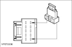
| C43: CHECK THE VOLTAGE SUPPLY TO INLINE FUSE F83 (15 A) FOR OPEN CIRCUIT |
| | 1 Connect Inline fuse F83 (15 A). |
| | 2 Ignition switch in position II. |
| | 3 Measure the voltage between inline fuse F83 (15 A) and ground. |
| | Does the meter display battery voltage? Yes No LOCATE AND RECTIFY the break in the voltage supply of inline fuse F83 (15 A) using the Wiring Diagrams. CHECK the operation of the system. |
| C44: CHECK THE VOLTAGE SUPPLY TO THE TRAILER CONTROL UNIT FOR OPEN CIRCUIT |
| | 1 Ignition switch in position 0. |
| | 2 Disconnect Trailer control unit from connector CAT18. |
| | 3 Ignition switch in position II. |
| | 4 Measure the voltage between the trailer control unit, connector CAT18, pin 1: - Box van / Bus / Combi: circuit SDF02A (RD), wiring harness side and ground.
- Platform truck: circuit SDF02A (BU/GN), wiring harness side and ground.
|
| | Does the meter display battery voltage? Yes No LOCATE and RECTIFY the break in the circuits between inline fuse F83 (15 A) and the trailer control unit using the Wiring Diagrams. CHECK the operation of the system. |
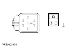
| C45: CHECK THE GROUND CONNECTION OF THE TRAILER CONTROL UNIT FOR OPEN CIRCUIT |
| | 1 Ignition switch in position 0. |
| | 2 Measure the resistance between the trailer control unit, connector CAT18, pin 5: - Box van / Bus / Combi: circuit C_GD149F (BK/GY), wiring harness side and ground.
- Platform truck: circuit B_GD119F (BK/BU), wiring harness side and ground.
|
| | Is a resistance of less than 2 Ohms registered? Yes No - Box van / Bus / Combi: LOCATE and RECTIFY the break in the circuits between trailer control unit and soldered connection S9D149 using the Wiring Diagrams. CHECK the operation of the system. - Platform truck: LOCATE and RECTIFY the break in the circuits between trailer control unit and soldered connection S2D119 using the Wiring Diagrams. CHECK the operation of the system. |
| C46: EXCLUDE THE TRAILER CONTROL UNIT AS THE CAUSE OF THE CONCERN |
| | 1 Ignition switch in position II. |
| | 2 SWITCH ON the hazard warning lamps. |
| | 3 Measure the voltage between trailer control unit, connector CAT18, pin 2: - Box van, bus, combi: circuit A_CLS23E (GY/OG), wiring harness side and ground.
- Chassis cab vehicle: circuit A_CLS23F (GY/OG), wiring harness side and ground.
|
| | Is fluctuating battery voltage measured? Yes RENEW the trailer control unit. CHECK the operation of the system. No RENEW the generic electronic module (GEM). CHECK the operation of the system. |