| Diagnosis and Testing Refer to Wiring Diagrams Section 417-01, for schematic and connector information. Special Tool(s) | | Set of adapter plugs for test probes 29-011A | Inspection and Testing NOTE:Before reading out the vehicle-specific data, remake all the electrical connections in the vehicle, so that communication between the module and WDS is ensured. NOTE:If the powertrain control module (PCM) is changed, the new one must be programmed. For this purpose, the vehicle-specific data is read out of the module to be replaced using WDS and is transferred to the new module.
REFER to: Modul-Konfiguration (418-01, General Procedures).
NOTE:The generic electronic module (GEM) forms part of the central junction box (CJB). NOTE:If the generic electronic module (GEM) is changed, the new one must be reinitialized. For this purpose, the vehicle-specific data is read out of the module to be replaced using WDS and is transferred to the new module. REFER to: Kommunikations-Netzwerk (418-00, Diagnosis and Testing), Zentralelektrikmodul (GEM) (419-10, Diagnosis and Testing). - Verify the customer concern.
- Visually check for any obvious mechanical or electrical damage.
Visual Inspection Chart | Mechanical | Electrical | - Adjustment of stoplamp switch
| - Fuse(s)
- Connector
- Wiring loom
| - Resolve any obvious causes or concerns found during the visual inspection before carrying out any further tests.
- If the cause of the concern cannot be found by visual inspection, continue with the symptom chart.
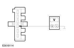
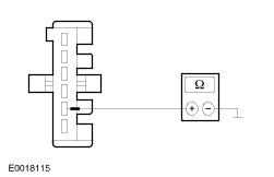
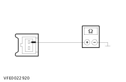
Symptom chart Symptom chart | Symptom | Possible Sources | Action | | All stoplamps inoperative | * Fuse(s) * Circuit(s) * Stoplamp switch * Central junction box (CJB) | * | | One or more stop lamps are inoperative | * Circuit(s) * Tail Lamp Assembly * Third stop light | * | | Stop lamps continuously lit | * Circuit(s) * Stoplamp switch * Anti-lock brake system module (ABS) * Electronic stability program (ESP) module * Powertrain control module (PCM) * Trailer socket | * | Pinpoint test NOTE:Use a digital multimeter for all electrical measurements. | PINPOINT TEST A : ALL STOPLAMPS INOPERATIVE | | TEST CONDITIONS | DETAILS/RESULTS/ACTIONS | | A1: CHECK FUSE F65 (15 A) (CJB) | | | 1 Ignition switch in position 0. | | | 2 Disconnect Fuse F65 (15 A) (CJB). | | | 3 CHECK Fuse F65 (15 A) (CJB). | | | Is the fuse OK? Yes No RENEW fuse F65 (15 A) (CJB). CHECK the operation of the system. If the fuse blows again, LOCATE and RECTIFY the short to ground using the Wiring Diagrams. CHECK the operation of the system. | | A2: CHECK THE VOLTAGE SUPPLY TO FUSE F65 (15 A) (CJB) FOR OPEN CIRCUIT | | | 1 Connect Fuse F65 (15 A) (CJB). | | | 2 Ignition switch in position II. | | | 3 Measure the voltage between fuse F65 (15 A) (CJB) and ground. | | | Does the meter display battery voltage? Yes No LOCATE AND RECTIFY the break in the voltage supply of fuse F65 (15 A) (CJB) with the aid of the wiring diagrams. CHECK the operation of the system. | | A3: CHECK THE VOLTAGE SUPPLY TO THE STOP LAMP SWITCH FOR OPEN CIRCUIT | | | 1 Ignition switch in position 0. | | | 2 Disconnect stop lamp switch from connector CCB08. | | | 3 Ignition switch in position II. | | | 4 Measure voltage between stop lamp switch, connector CCB08, pin 1, circuit SBP65A (RD), wiring harness side and ground. | | | Does the meter display battery voltage? Yes No | | A4: STOP LAMP SWITCH INSPECTION | | | 1 Ignition switch in position 0. | | | 2 Connect fused (15 A) jumper wire at stop lamp switch, connector CCB08, between pin 1, circuit SBP65A (RD) and pin 2, circuit CCB08A (VT/WH), wiring harness side. | | | 3 Ignition switch in position II. | | | 4 Check the stop lamps. | | | Do the stop lamps come on? Yes RENEW stop light switch. CHECK the operation of the system. No - Box van, bus, combi: LOCATE and RECTIFY the break in the circuit between the stop lamp switch and soldered connection S2CB08 using the Wiring Diagrams. CHECK the operation of the system. | | A5: CHECK COMMON GROUND SUPPLY TO THE REAR LAMP CLUSTERS FOR OPEN CIRCUIT | | | 1 Ignition switch in position 0. | | | 2 Disconnect Left-hand rear lamp assembly from connector CLS35 (CLS04). | | | 3 Measure the resistance between the left-hand rear lamp assembly, connector CLS35 (CLS04), pin 1, circuit B_GD129U (BK/YE), wiring harness side and ground. | | | Is a resistance of less than 2 Ohms registered? Yes LOCATE and RECTIFY the break in the circuit between the stop lamp switch and soldered connection S4CB08 using the Wiring Diagrams. CHECK the operation of the system. No LOCATE and RECTIFY the break in the circuit between soldered connection S4D129G and ground connection G29 with the aid of the Wiring Diagrams. CHECK the operation of the system. | | A6: CHECK CIRCUIT BETWEEN CENTRAL JUNCTION BOX (CJB) AND BRAKE LAMP SWITCH FOR OPEN CIRCUIT | | | 1 Ignition switch in position 0. | | | 2 Disconnect Central junction box (CJB). - Box van / Bus / Combi: from connector C2BP02B
- Platform truck: from connector CBP02B
| | | 3 Measure the resistance between the stop lamp switch, connector CCB08, pin 1, circuit SBP65A (RD), wiring harness side and the central junction box (CJB). - Box van / Bus / Combi: Connector C2BP02B, pin 13, circuit SBP65A (RD), wiring harness side.
- Platform truck: Connector CBP02B, pin 13, circuit SBP65A (RD), wiring harness side.
| | | Is a resistance of less than 2 Ohms registered? Yes CHECK and if necessary RENEW the central junction box (CJB). CHECK the operation of the system. No LOCATE and RECTIFY break in circuit between central junction box (CJB) and stop lamp switch using the Wiring Diagrams. CHECK the operation of the system. | | PINPOINT TEST B : ONE OR MORE STOP LAMPS ARE INOPERATIVE | | TEST CONDITIONS | DETAILS/RESULTS/ACTIONS | | B1: DETERMINE THE INOPERATIVE STOP LAMP(S) | NOTE:The fused jumper wire remains connected in the following test steps. | | | 1 Ignition switch in position II. | | | 2 Disconnect stop lamp switch from connector CCB08. | | | 3 Connect fused (15 A) jumper wire at stop lamp switch, connector CCB08, between pin 1, circuit SBP65A (RD) and pin 2, circuit CCB08A (VT/WH), wiring harness side. | | | 4 Ignition switch in position II. | | | 5 Check the stop lamps. | | | Is the right-hand stoplamp inoperative? Yes No - Left-hand stoplamp inoperative: GO to B4. - Additional high-mounted stop lamp inoperative: GO to B6. - Left-hand stoplamp and additional high-mounted stoplamp inoperative: GO to B8. | | B2: CHECK THE VOLTAGE SUPPLY TO THE RIGHT-HAND REAR LAMP ASSEMBLY FOR OPEN CIRCUIT | | | 1 Ignition switch in position 0. | | | 2 Disconnect Right-hand rear lamp assembly. - Box van / Bus / Combi: from connector CLS26
- Platform truck: from connector CLS36
| | | 3 Ignition switch in position II. | | | 4 Box van, bus, combi: Measure voltage between right-hand rear lamp assembly, connector CLS26: - Vehicles without tailgate or without trailer socket: pin 4, circuit CCB08G (VT/WH), wiring harness side and ground.
- Vehicles with tailgate or with trailer socket: pin 4, circuit CCB08AB (VT/WH), wiring harness side and ground.
| | | 5 Platform truck: Measure the voltage between right-hand rear lamp assembly, connector CLS36, pin 2, circuit CCB08G (VT/WH), wiring harness side and ground. | | | Does the meter display battery voltage? Yes No - Chassis cab vehicle: LOCATE and RECTIFY the break in the circuit between soldered connection S4CB08 and rear lamp assembly using the Wiring Diagrams. CHECK the operation of the system. - All other models: LOCATE and RECTIFY the break in the circuit between soldered connection S2CB08 and rear lamp assembly using the Wiring Diagrams. CHECK the operation of the system. | | B3: CHECK THE GROUND CONNECTION TO THE RIGHT-HAND REAR LAMP ASSEMBLY FOR OPEN CIRCUIT | | | 1 Ignition switch in position 0. | | | 2 Box van, bus, combi: Measure resistance between right-hand rear lamp assembly, connector CLS26: - vehicles without tailgate, pin 5, circuit A_GD151H (BK/GN), wiring harness side and ground.
- Vehicles with tailgate or with trailer socket: pin 5, circuit A_GD151AB (BK/GN), wiring harness side and ground.
| | | 3 Platform truck: Measure the resistance between the right-hand rear lamp assembly, connector CLS36, pin 1, circuit B_GD129V (BK/YE), wiring harness side and ground. | | | Is a resistance of less than 2 Ohms registered? Yes RENEW the rear lamp assembly. CHECK the operation of the system. No - Chassis cab vehicle: LOCATE and RECTIFY the break in the circuit between rear lamp assembly and soldered connection S4D129G using the Wiring Diagrams. CHECK the operation of the system. - All other vehicles: LOCATE and RECTIFY the break in the circuit between the rear lamp assembly and ground connection G51 using the Wiring Diagrams. CHECK the operation of the system. | | B4: CHECK THE VOLTAGE SUPPLY TO THE LEFT-HAND REAR LAMP ASSEMBLY FOR OPEN CIRCUIT | | | 1 Ignition switch in position 0. | | | 2 Disconnect left-hand rear lamp assembly:. - Box van, bus, combi: from connector CLS22
- Platform truck: from connector CLS35
| | | 3 Ignition switch in position II. | | | 4 Box van, bus, combi: Measure voltage between left-hand rear lamp assembly, connector CLS22, pin 4: - Vehicles with double doors: circuit CCB08L (VT/WH), wiring harness side and ground.
- All other vehicles: circuit CCB08Z (VT/WH), wiring harness side and ground.
| | | 5 Platform truck: Measure the voltage between left-hand rear lamp assembly, connector CLS35, pin 2, circuit CCB08H (VT/WH), wiring harness side and ground. | | | Does the meter display battery voltage? Yes No - Van, bus, combi with double doors: LOCATE and RECTIFY the break in the circuit between soldered connection S4CB08A and rear lamp assembly using the Wiring Diagrams. CHECK the operation of the system. - Box van, bus, combi vehicles with tailgate or with trailer socket: LOCATE and RECTIFY the break in the circuit between soldered connection S2CB08A and rear lamp assembly using the Wiring Diagrams. CHECK the operation of the system. - Chassis cab vehicle: LOCATE and RECTIFY the break in the circuit between soldered connection S4CB08 and rear lamp assembly using the Wiring Diagrams. CHECK the operation of the system. | | B5: CHECK THE GROUND CONNECTION TO THE LEFT-HAND REAR LAMP ASSEMBLY FOR OPEN CIRCUIT | | | 1 Ignition switch in position 0. | | | 2 Box van, bus, combi: Measure resistance between left-hand rear lamp assembly, connector CLS22, pin 5: - Vehicles without tailgate: circuit A_GD149N (BK/GY), wiring harness side and ground.
- All other vehicles: circuit A_GD149C (BK/GY), wiring harness side and ground.
| | | 3 Platform truck: Measure the resistance between the left-hand rear lamp assembly, connector CLS35, pin 1, circuit B_GD129U (BK/YE), wiring harness side and ground. | | | Is a resistance of less than 2 Ohms registered? Yes RENEW the left-hand rear lamp assembly. CHECK the operation of the system. No - Box van, bus, combi vehicles with tailgate or with tow bar socket: LOCATE and RECTIFY the break in the circuit between rear lamp assembly and soldered connection S4D149A, using the Wiring Diagrams. CHECK the operation of the system. - Van, bus, combi, all other variants: LOCATE and RECTIFY the break in the circuit between rear lamp assembly and soldered connection S4D149B using the Wiring Diagrams. CHECK the operation of the system. - Chassis cab vehicle: LOCATE and RECTIFY the break in the circuit between rear lamp assembly and soldered connection S4D149G, using the Wiring Diagrams. CHECK the operation of the system. | | B6: CHECK THE VOLTAGE SUPPLY OF THE ADDITIONAL HIGH-MOUNTED STOPLAMP FOR OPEN CIRCUIT (BOX VAN, BUS, COMBI) | | | 1 Ignition switch in position 0. | | | 2 Disconnect Additional high-mounted stoplamp from connector CLS17(L). | | | 3 Ignition switch in position II. | | | 4 Measure the voltage between high mounted stoplamp: - Vehicles without tailgate, without trailer socket: Connector CLS17, pin 1, circuit CCB08N (VT/WH), wiring harness side and ground.
- All other vehicles: Connector CLS17L, pin 1, circuit CCB08AG (VT/WH), wiring harness side and ground.
| | | Does the meter display battery voltage? Yes No - Vehicles without tailgate, without trailer socket: LOCATE and RECTIFY the break in the circuit between soldered connection S4CB08A and the additional high-mounted stoplamp using the wiring diagrams. CHECK the operation of the system. - All other vehicles: LOCATE and RECTIFY the break in the circuit(s) between soldered connection S4CB08 and the additional high-mounted stop lamp using the Wiring Diagrams. CHECK the operation of the system. | | B7: CHECK THE GROUND CONNECTION OF THE ADDITIONAL HIGH-MOUNTED STOPLAMP FOR OPEN CIRCUIT | | | 1 Ignition switch in position 0. | | | 2 Measure the resistance between high mounted stoplamp: - Vehicles without tailgate, without trailer socket: Connector CLS17, pin 2, circuit A_GD149AE (BK/GY), wiring harness side and ground.
- All other vehicles: connector CLS17L, pin 2, circuit A_GD151BE (BK/GN), wiring harness side, and ground.
| | | Is a resistance of less than 2 Ohms registered? Yes RENEW additional high-mounted stop lamp. CHECK the operation of the system. No - Vehicles without tailgate, without trailer socket: LOCATE and RECTIFY the break in the circuit between the additional high-mounted stop lamp and soldered connection S4D149B using the Wiring Diagrams. CHECK the operation of the system. - All other vehicles: LOCATE and RECTIFY the break in the circuit between the additional high-mounted stop lamp and soldered connection S4D149A using the Wiring Diagrams. CHECK the operation of the system. | | B8: CHECK COMMON VOLTAGE SUPPLY OF REAR LEFT-HAND LAMP CLUSTER AND ADDITIONAL HIGH-MOUNTED STOP LAMP FOR OPEN CIRCUIT | | | 1 Ignition switch in position 0. | | | 2 Disconnect Left-hand rear lamp assembly from connector CLS22. | | | 3 Ignition switch in position II. | | | 4 Measure the voltage between left-hand rear lamp assembly, connector CLS22, pin 4, circuit CCB08L (VT/WH), wiring harness side and ground. | | | Does the meter display battery voltage? Yes LOCATE and RECTIFY the break in the circuit between soldered connection S4D149B and ground connection G49 with the aid of the Wiring Diagrams. CHECK the operation of the system. No LOCATE and RECTIFY the break in the circuit between soldered connection S2CB08 and soldered connection S4CB08A using the Wiring Diagrams. CHECK the operation of the system. | | PINPOINT TEST C : STOP LAMPS CONTINUOUSLY LIT | | TEST CONDITIONS | DETAILS/RESULTS/ACTIONS | | C1: STOP LAMP SWITCH INSPECTION | | | 1 Ignition switch in position 0. | | | 2 Disconnect stop lamp switch from connector CCB08. | | | 3 Ignition switch in position II. | | | 4 Check the stop lamps. | | | Do the stoplamps light up continuously? Yes No RENEW brake light switch. CHECK the operation of the system. | | C2: DETERMINE THE EQUIPMENT LEVEL OF THE VEHICLE | | | 1 Determine the equipment level of the vehicle. | | | Does the vehicle have ABS/ESP? Yes No | | C3: ELIMINATE THE ABS MODULE/ESP MODULE AS CAUSE FOR THE SHORT TO BATTERY VOLTAGE | | | 1 Ignition switch in position 0. | | | 2 Disconnect fuse F13 (40 A) (EJB). | | | 3 Disconnect fuse F20 (10 A) (EJB). | | | 4 Disconnect fuse F21 (25 A) (EJB). | | | 5 Ignition switch in position II. | | | 6 Check the stop lamps. | | | Do the stoplamps light up continuously? Yes No RENEW anti-lock braking system (ABS) module or electronic stability program (ESP) module. CHECK the operation of the system. | | C4: RULE OUT THE POWERTRAIN CONTROL MODULE (PCM) AS POSSIBLE CAUSE FOR A SHORT TO BATTERY VOLTAGE | | | 1 Ignition switch in position 0. | | | 2 Connect fuse F13 (40 A) (EJB). | | | 3 Connect fuse F20 (10 A) (EJB). | | | 4 Connect fuse F21 (25 A) (EJB). | | | 5 Disconnect fuse F26 (15 A) (EJB). | | | 6 Disconnect fuse F37 (5 A) (EJB). | | | 7 Disconnect Deisel vehicles only: fuse F27 (10 A) (EJB). | | | 8 Ignition switch in position II. | | | 9 Check the stop lamps. | | | Do the stoplamps light up continuously? Yes LOCATE and RECTIFY the short to battery voltage in the circuits connected to soldered connection S2CB08 using the Wiring Diagrams. CHECK the operation of the system. Vehicles with trailer socket: CHECK and if necessary RENEW the tow bar socket. CHECK the operation of the system. No RENEW the PCM. CHECK the operation of the system. | |