
Cam angle sensor - r.r.
- Make
- Lancia
- Model
- Thesis Factory Service Manual
- Year
- 2002–2009
- Section
- Petrol fuel injection system › Cam angle sensor - r.r.
CAM ANGLE SENSOR - R.R.
Removing
- Position the vehicle on a lift.
- Open the boot, remove the cover on the left hand side and disconnect the negative battery lead.
See in Op. 7040D50 ENGINE COMPARTMENT UPPER SOUND INSULATION SHIELD - R.R.
See in Op. 4450B04 Right FRONT WHEEL (one) - R.R.
- Raise the vehicle on the lift.
See in Op. 7055B54 PROTECTION/GUARD under engine - R.R.
See in Op. 7055B42 FRONT WHEEL ARCH LINER (one), left or right - R.R.
See in Op. 7055B64 Engine compartment DUST SEAL in front wheel arch (one), left or right - R.R.
See in Op. 1048A28 vacuum air circuit resonator pipe - r+r
See in Op. 1048A21 AIR INLET HOSE FROM INTAKE TO FILTER - R.R.
See in Op. 1048A23 Cold AIR INTAKE for air filter - R.R.
See in Op. 1048A10 COMPLETE AIR FILTER -R.R.
See in Op. 1048A21 AIR INLET HOSE FROM INTAKE TO FILTER - R.R.
See in Op. 1048A50 air inlet pipe to turbocharger - r + r
See in Op. 1048A10 COMPLETE AIR FILTER -R.R.
See in Op. 1016A40 Ignition COIL COVER on cylinder head - R.R.
See in Op. 1092G10 Engine components single drive BELT - R.R.
See in Op. 1092A10 Crankshaft PULLEY - R.R. for versions with air conditioner
See in Op. 1032D12 Timing system protective COVER(S) - R.R.
See in Op. 1032B10 TOOTHED timing BELT - R.R. for timing adjustment or replacement
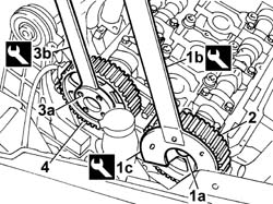
1. Undo the bolt (1a) for the exhaust side timing driven pulley using the tools (1b) and (1c) for counter-torque.
| Description | Code | Function | |
|---|---|---|---|
| 1b | Support for counter-torque | 1.860.831.000 | Loosen/tighten driven toothed pulley bolt |
| Description | Code | Function | |
|---|---|---|---|
| 1c | Spanner for rotating timing pullies | 1.860.831.002 | Loosen/tighten camshaft drive pulley bolt |
2. Remove the exhaust side timing driven pulley.
3. Undo the inlet side timing driven pulley bolts (3a) using the tool (3b) for counter-torque.
| Description | Code | Function | |
|---|---|---|---|
| 3b | Counter-torque | 1.860.856.000 | Loosen/tighten inlet side camshaft drive pulley bolts |
4. Remove the inlet side timing driven pulley.
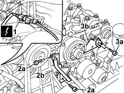
1. Disconnect the electrical connection for the cam angle sensor.
| Description | Connector | |
|---|---|---|
| 1 | Timing sensor | K047 |
2. Undo the bolts (2a) and remove the guard (2b).
3. Undo the bolts (3a) and remove the cam angle sensor (3b).
Refitting
- Position the cam angle sensor and secure it using the bolts.
| Value - daNm | Fastening | Component | Ø | |
|---|---|---|---|---|
| 0.9 | Bolt | CAM ANGLE SENSOR CAMSHAFT | M6 |
- Position the cam angle sensor wiring and fit the guard.
- Connect the electrical connection for the cam angle sensor.
| Description | Connector | |
|---|---|---|
| Timing sensor | K047 |
- Position the inlet side timing driven pulley and secure it without tightening the bolts.
- Position the exhaust side timing driven pulley and secure it without tightening the bolt.
The bolts securing the pullies are tightened when refitting the timing drive belt.
See in Op. 1032B10 TOOTHED timing BELT - R.R. for timing adjustment or replacement
See in Op. 1032D12 Timing system protective COVER(S) - R.R.
See in Op. 1092A10 Crankshaft PULLEY - R.R. for versions with air conditioner
See in Op. 1092G10 Engine components single drive BELT - R.R.
See in Op. 1016A40 Ignition COIL COVER on cylinder head - R.R.
See in Op. 1048A10 COMPLETE AIR FILTER -R.R.
See in Op. 1048A50 air inlet pipe to turbocharger - r + r
See in Op. 1048A21 AIR INLET HOSE FROM INTAKE TO FILTER - R.R.
See in Op. 1048A10 COMPLETE AIR FILTER -R.R.
See in Op. 1048A23 Cold AIR INTAKE for air filter - R.R.
See in Op. 1048A21 AIR INLET HOSE FROM INTAKE TO FILTER - R.R.
See in Op. 1048A28 vacuum air circuit resonator pipe - r+r
See in Op. 7055B64 Engine compartment DUST SEAL in front wheel arch (one), left or right - R.R.
See in Op. 7055B42 FRONT WHEEL ARCH LINER (one), left or right - R.R.
- Lower the vehicle on the lift.
See in Op. 4450B04 Right FRONT WHEEL (one) - R.R.
- Connect the negative battery lead.
See in Op. 0010T20 Engine REFRIGERANT FLUID - Change
See in Op. 7055B54 PROTECTION/GUARD under engine - R.R.
See in Op. 7040D50 ENGINE COMPARTMENT UPPER SOUND INSULATION SHIELD - R.R.
- Remove the vehicle from the lift.
Removing
See in Op. 5530B10 BATTERY - R.R.
- Make sure that the ignition key is in the OFF position, then disconnect the negative battery terminal (-).
- [7040D12]
- [7040D14]
See in Op. 1048A28 vacuum air circuit resonator pipe - r+r
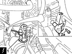
1. Disconnect the electrical connection from the cam angle sensor and release the wiring from the retaining bands.
| Description | Connector | |
|---|---|---|
| 1 | Timing sensor | K047 |
2. Undo the bolts (2a) and remove the cam angle sensor (2b).
Refitting
- Fit the cam angle sensor and secure it using the bolts.
- Connect the electrical connection to the cam angle sensor and secure the wiring to the retaining bands.
| Description | Connector | |
|---|---|---|
| Timing sensor | K047 |
See in Op. 1048A28 vacuum air circuit resonator pipe - r+r
- [7040D14]
- [7040D12]
- Connect the negative battery terminal.
Parts & tools for this job For 2002 Lancia Thesis
- TOOLOBD2 scannerSearch: OBD2 scanner
- TOOLDigital multimeterSearch: automotive digital multimeter
- TOOLBack-probe test leadsSearch: back probe test leads
Links open Amazon search results in a new tab. As an Amazon Associate I earn from qualifying purchases.