
Upper track control arm support
- Make
- Lancia
- Model
- Thesis Factory Service Manual
- Year
- 2002–2009
- Section
- Front suspension › Upper track control arm support
Upper track control arm support
Removing
- Position the vehicle on a lift.
- Disconnect the negative battery terminal.
See in Op. 7040D50 ENGINE COMPARTMENT UPPER SOUND INSULATION SHIELD - R.R.
See in Op. 4450B04 Right FRONT WHEEL (one) - R.R.
See in Op. 7055B42 FRONT WHEEL ARCH LINER (one), left or right - R.R.
See in Op. 7055B64 Engine compartment DUST SEAL in front wheel arch (one), left or right - R.R.
See in Op. 4410B73 Front and rear upper track control ARMS - R.R.
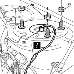
1. Disconnect the electrical connection for the left or right front vertical acceleration sensor.
| Description | Connector | |
|---|---|---|
| 1 | Left front vertical acceleration sensor | K006 |
| Description | Connector | |
|---|---|---|
| 1 | Right front vertical acceleration sensor | K007 |
Take care not to bend the connector tab
2. Undo the fixing nuts (2a) releasing the front suspension spring/shock absorber assembly (2b) from the fastening on the turret.
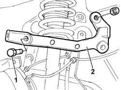
1. Undo the bolts and the nut fixing the upper track control arm support.
- Move the spring/shock absorber assembly to the side.
2. Remove the upper track control arm support.
Refitting
- Position the track control arm support and secure it using the fixing bolts.
- Position the spring/shock absorber assembly and fasten it using the fixing nuts.
| Value - daNm | Fastening | Component | Ø | |
|---|---|---|---|---|
| (turret) 4 | Nut | M10 x1,25 |
- Connect the electrical connection for the left or right front vertical acceleration sensor.
| Description | Connector | |
|---|---|---|
| Left front vertical acceleration sensor | K006 |
| Description | Connector | |
|---|---|---|
| Right front vertical acceleration sensor | K007 |
Check that the two connectors are properly fitted, then, acting on the connectors and not on the wires, pull the connectors gently and check that they do not release and the fastening is secure.
See in Op. 4410B73 Front and rear upper track control ARMS - R.R.
See in Op. 4450B04 Right FRONT WHEEL (one) - R.R.
- Place the vehicle in Standard "A" conditions, in other words with the vehicle mass complete, spare wheel, tool kit, all supplies and accessories (oil, engine coolant, etc.) and a full fuel tank.
- Check that the tyre inflation pressure is correct.
- Position the vehicle on a support so that the wheels are resting on the ground.
- Check that after having place the vehicle in standard "A" conditions, the measurement "A"-"B" corresponds to the figure given in the table below.
| Subject | Value | |
|---|---|---|
| Front wheel geometry | mm | |
| A - B | 165 ± 5 | |
| Standard A |
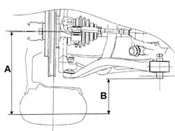
- Check that after having place the vehicle in standard "A" conditions, the measurement "A"-"B" corresponds to the figure given in the table below.
| Subject | Value | |
|---|---|---|
| Front wheel geometry | mm | |
| A - B | 165 ± 5 | |
| Standard A |
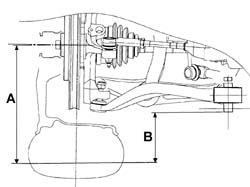
- Check that after having place the vehicle in standard "A" conditions, the measurement "A"-"B" corresponds to the figure given in the table below.
| Subject | Value | |
|---|---|---|
| Front wheel geometry | mm | |
| A - B | 162 ± 5 | |
| Standard A |
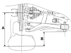
- Check that after having place the vehicle in standard "A" conditions, the measurement "A"-"B" corresponds to the figure given in the table below.
| Subject | Value | |
|---|---|---|
| Front wheel geometry | mm | |
| A - B | 163±5 |
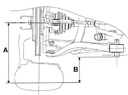
- Check that after having place the vehicle in standard "A" conditions, the measurement "A"-"B" corresponds to the figure given in the table below.
| Subject | Value | |
|---|---|---|
| Front wheel geometry | mm | |
| A - B | 162 ± 5 | |
| Standard A |
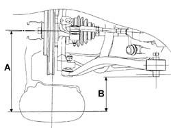
See in Op. 7055B64 Engine compartment DUST SEAL in front wheel arch (one), left or right - R.R.
See in Op. 7055B42 FRONT WHEEL ARCH LINER (one), left or right - R.R.
- Connect the negative battery terminal.
- Remove the vehicle from the lift.
See in Op. 7040D50 ENGINE COMPARTMENT UPPER SOUND INSULATION SHIELD - R.R.
Parts & tools for this job For 2002 Lancia Thesis
- TOOLCoil spring compressorSearch: coil spring compressor
- TOOLBall joint separatorSearch: ball joint separator
- PARTFront shock absorbersSearch: Lancia Thesis 2002 front shock absorbers
Links open Amazon search results in a new tab. As an Amazon Associate I earn from qualifying purchases.