
Toothed timing belt - r r with engine removed
- Make
- Lancia
- Model
- Ypsilon Factory Service Manual
- Year
- 2003–2011
- Section
- Timing system › Toothed timing belt - r r with engine removed
Toothed timing belt - r r with engine removed
Removing
- 1004D40 engine - position on stand and remove
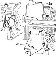
1. Undo the bolt (1a) and remove the engine oil dipstick.
2. Remove the upper shield (2a) and the lower shield (2b) for the timing drive belt.
3. Disconnect the electrical connection, release the electrical cable for the rpm and T.D.c. sensor from the fastenings on the protective timing belt covers and remove the rpm sensor.
| Name | Connector | |
|---|---|---|
| Rpm sensor | K46 |
Removing
- 1004D40 engine - position on stand and remove
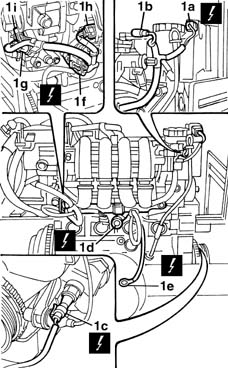
1. Disconnect electrical connections (1a), (1b), (1c), (1d), (1e), (1f), (1g), (1h) and (1i).
2. Open the wiring duct (2a) and remove the engine wiring (2b).
| Name | Connector | |
|---|---|---|
| 1a | Rpm sensor | K46 |
| Name | Connector | |
|---|---|---|
| 1b | Integrated air temperature sensor | K43 |
| Name | Connector | |
|---|---|---|
| 1c | Engine oil pressure sensor (switch) | K30 |
| Name | Connector | |
|---|---|---|
| 1d | Detonation sensor | K50 |
| Name | Connector | |
|---|---|---|
| 1e | Earth on engine | C40 |
| Name | Connector | |
|---|---|---|
| 1f | Injector junction | D81 |
| Name | Connector | |
|---|---|---|
| 1g | Engine temperature sender unit | K36 |
| Name | Connector | |
|---|---|---|
| 1h | Fuel vapour recovery solenoid | L10 |
| Name | Connector | |
|---|---|---|
| 1i | Integrated throttle body actuator | N75 |
Removing
- 1004D40 engine - position on stand and remove
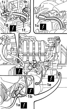
1. Disconnect electrical connections (1a), (1b), (1c), (1d), (1e), (1f), (1g), (1h) and (1i).
| Name | Connector | |
|---|---|---|
| 1a | Rpm sensor | K46 |
| Name | Connector | |
|---|---|---|
| 1b | Engine oil pressure sensor (switch) | K30 |
| Name | Connector | |
|---|---|---|
| 1c | Integrated air temperature sensor | K43 |
| Name | Connector | |
|---|---|---|
| 1d | Detonation sensor | K50 |
| Name | Connector | |
|---|---|---|
| 1e | Earth on engine | C40 |
| Name | Connector | |
|---|---|---|
| 1f | Injector junction | D81 |
| Name | Connector | |
|---|---|---|
| 1g | Engine temperature sender unit | K36 |
| Name | Connector | |
|---|---|---|
| 1h | Fuel vapour recovery solenoid | L10 |
| Name | Connector | |
|---|---|---|
| 1i | Integrated throttle body actuator | N75 |
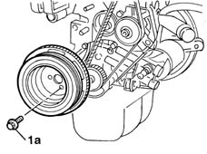
1. Undo the bolts (1a) and remove the auxiliary shaft pulley on the crankshaft.
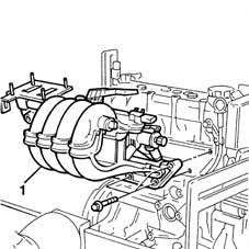
1. Remove the inlet manifold complete with injectors and butterfly casing.
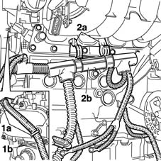
1. Open clips (1a) and release wire (1b).
2. Open retaining clips (2a) and release engine wiring bundle retaining channel (2b).
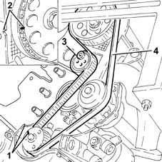
1. Rotate the toothed pulley so that the timing notches are aligned.
2. Check that the timing reference on the timing driven pulley is aligned with the reference on the cylinder head.
3. Loosen the timing belt moving tensioner nut.
4. Remove the timing drive belt.
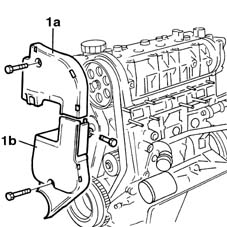
1. Remove the upper shield (1a) and the lower shield (1b) for the timing belt.
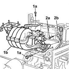
1. Undo the bolts (1a) and remove the inlet manifold (1b) with injectors and throttle body.
2. Undo the bolt (2a) and remove the engine oil dipstick pipe (2b).
Refitting
Check that the timing references on the driven pulley and the drive pulley are still aligned during the removal.
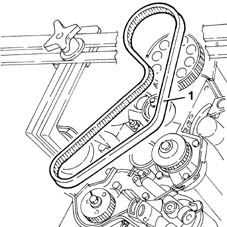
1. Fit the timing belt.
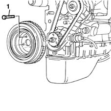
1. Undo the bolts indicated and remove the auxiliary shaft drive pulley on the crankshaft.
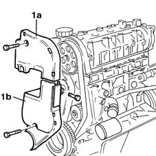
1. Remove the upper shield (1a) and the lower shield (1b) for the timing belt.
Remove the engine wiring harness.
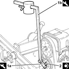
1. Fit the tools (1a) and (1b) on the timing belt moving tensioner.
The weight for the tool (1b) should have the knurled part removed and should be positioned 65 mm away on the millimetric rod.
The millimetric rod should be placed in a horizontal position acting on the tool joint.
| Name | Country | |
|---|---|---|
| 1a | Belt tensioner | 1.860.745.300 |
| Name | Country | |
|---|---|---|
| 1b | Belt tensioner | 1.860.745.100 |
Let the timing belt bed in by rotating the crankshaft through two revolutions in its direction of rotation.
During this stage the millimetric rod may move away from the horizontal position; if this is the case, adjust the joint on the tool and repeat the operation.
2. Tighten the nut fixing the timing belt moving tensioner to the recommended torque.
| Fastening | Component | Ø | Value (daNm) | |
|---|---|---|---|---|
| 2 | Nut | MOBILE TIMING TENSIONER | M8 x 1.25 | 2.8 |
Remove the protective cover for the camshaft rear gears.
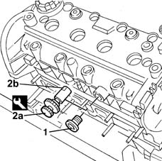
1. Undo the camshaft housing side plugs.
2. Position the tools (1a) in the housings for the plugs undone previously, then rotate the camshafts until the splining on each camshaft coincides with the pin (2b) for the tools. The camshafts will be timed in this way.
| Name | Country | |
|---|---|---|
| 2a | Locating pin | 1.860.985.000 |
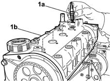
1. Unscrew and remove spark plugs (1a) from the seats on the cylinder head (1b).
Refit the lower shield and the upper shield for the timing drive belt.
Fit the auxiliary shaft drive pulley on the crankshaft and tighten the fixing bolts to the recommended torque.
| Fastening | Component | Ø | Value (daNm) | |
|---|---|---|---|---|
| Bolt | CRANKSHAFT PULLEY | M8 x 1.25 | 2.2 |
Fit the rpm and TDC sensor and secure it using the bolt and reconnect the connection.
| Name | Connector | |
|---|---|---|
| Rpm sensor | K46 |
Fit the engine oil dipstick.
- 1004D40 engine - position on stand and remove
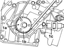
1. Check that the centering lug (1a) on the crankshaft gear (1b) is positioned opposite the housing for the rpm and TDC sensor (1c). The pistons will be approximately aligned with one another in this position.
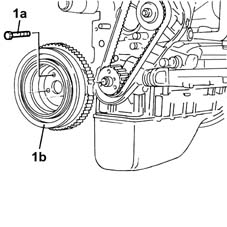
1. Undo the fixing bolts (1a) and remove the auxiliary shaft drive pulley (1b).
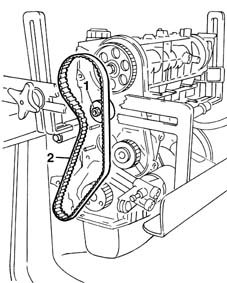
1. Loosen the nut fixing the automatic belt tensioner.
2. Remove the timing drive belt.
Remove the protective cover for the camshaft rear gears.
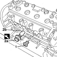
1. Undo the camshaft housing side plugs.
2. Position the tools (1a) in the housings for the plugs undone previously, then rotate the camshafts until the splining on each camshaft coincides with the pin (2b) for the tools. The camshafts will be timed in this way.
| Name | Country | |
|---|---|---|
| 2a | Locating pin | 1.860.985.000 |
Refitting
Remove the spark plugs for cylinders 1 and 2.
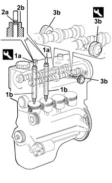
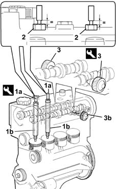
1. Position the tools (1a) in the housings for the spark plug for cylinders 1 and 2, tightening the components (1b) to a torque of 0.5 daNm.
2. Rotate the crankshaft in its normal direction of rotation, using small movements, until the surface (2a) on the moving part of the tool is aligned with the plane (2b) on the fixed part in the spark plug housing. When both tools positioned in the spark plug housing are in this condition the pistons will be aligned, i.e. halfway through their stroke and the piston for cylinder 1 will be descending, i.e. in the inlet stroke.
The pistons were already approximately aligned previously.
Rotate the crankshaft gradually to prevent the pins for the tools being expelled by the piston compression.
The camshafts were timed previously through the fitting of the tools (3b).
| Name | Country | |
|---|---|---|
| 1a | Bearings | 1.860.992.000 |
| Name | Country | |
|---|---|---|
| 3b | Locating pin | 1.860.985.000 |
1. Check that the centering lug (1a) on the crankshaft gear (1b) is positioned opposite the housing for the rpm and TDC sensor (1c). The pistons will be approximately aligned with one another in this position.
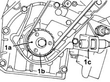
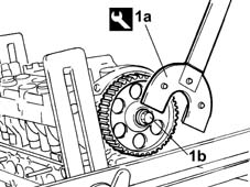
1. Using the locking tools (1a), loosen the bolts (1b) fixing the camshaft drive pulley.
| Name | Country | |
|---|---|---|
| 1a | Support for counter-torque | 1.860.831.000 |
| Name | Country | |
|---|---|---|
| 1a | Spanner for camshaft pulley rotation | 1.860.831.002 |
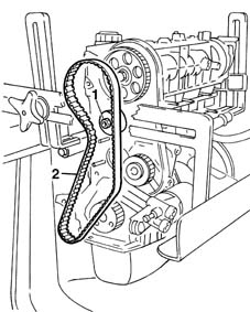
1. Loosen the nut fixing the automatic belt tensioner.
2. Remove the timing drive belt.
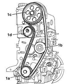
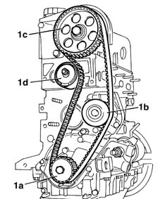
1. Proceed with fitting the timing drive belt, fitting it initially on the crankshaft gear (1a), the water pump pulley (1b), the camshaft drive pulley (1c) and, lastly, on the belt tensioner pulley (1d).
Make sure that this operation is carried out with the camshaft pulley (1c) slack.
Refitting
Remove the spark plugs for cylinders 1 and 2.
1. Position the tools (1a) in the housings for the spark plug for cylinders 1 and 2, tightening the components (1b) to a torque of 0.5 daNm.
2. Turn the crankshaft in the normal sense of rotation until the tool mobile parts are aligned. When both tools positioned in the spark plug housing are in this condition the pistons will be aligned, i.e. halfway through their stroke and the piston for cylinder 1 will be descending, i.e. in the inlet stroke.
The pistons were already approximately aligned previously.
Rotate the crankshaft gradually to prevent the pins for the tools being expelled by the piston compression.
The camshafts were timed previously through the fitting of the tools (3).
| Name | Country | |
|---|---|---|
| 1a | Bearings | 1.860.992.000 |
| Name | Country | |
|---|---|---|
| 3 | Locating pin | 1.860.985.000 |
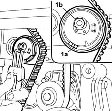
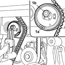
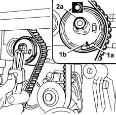
1. Using suitable pliers, rotate the automatic tensioner placing it in the maximum tension position, i.e. with the moving reference (1a) positioned as illustrated in the diagram then lock the nut (1d) fixing the tensioner to the support.
1. Using the locking tools (1a), loosen the bolts (1b) fixing the camshaft drive pulley.
| Name | Country | |
|---|---|---|
| 1a | Support for counter-torque | 1.860.831.000 |
| Name | Country | |
|---|---|---|
| 1a | Spanner for camshaft pulley rotation | 1.860.831.002 |
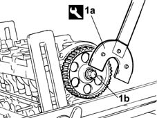
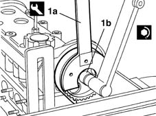
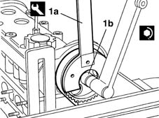
1. Using the tool (1a) tighten the bolt (1b) fixing the camshaft pulley to the recommended torque.
| Name | Country | |
|---|---|---|
| 1a | Support for counter-torque | 1.860.831.000 |
| Name | Country | |
|---|---|---|
| 1a | Spanner for camshaft pulley rotation | 1.860.831.002 |
| Fastening | Component | Ø | Value (daNm) | |
|---|---|---|---|---|
| 1b | Bolt | TIMING GEAR DRIVEN PULLEYS | M12 x 1.25 | 12 |
Remove the tools positioned previously for timing and locking the camshafts and rotate the crankshaft through two revolutions in its direction of rotation to let the timing drive belt bed in.
1. Proceed with fitting the timing drive belt, fitting it initially on the crankshaft gear (1a), the water pump pulley (1b), the camshaft drive pulley (1c) and, lastly, on the belt tensioner pulley (1d).
Make sure that this operation is carried out with the camshaft pulley (1c) slack.
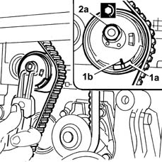
1. Loosen the nut fixing the tensioner and ensure that the moving reference (1a) coincides with the fixed reference (1b) retaining the tensioner using the special pliers so as not to release the tension suddenly.
2. Once the two references are aligned, tighten the nut (2a) fixing the tensioner to the recommended torque.
Rotate the crankshaft through a further two revolutions in its direction of rotation, then repositino the tools used for timing the engine and check that the timing is correct.
Refit the side plugs in the camshaft housing.
| Fastening | Component | Ø | Value (daNm) | |
|---|---|---|---|---|
| 2a | Nut | MOBILE TIMING TENSIONER | M8 | 2.5 |
1. Using suitable pliers, rotate the automatic tensioner placing it in the maximum tension position, i.e. with the moving reference (1a) positioned as illustrated in the diagram then lock the nut (1d) fixing the tensioner to the support.
Refit the lower shield and the upper shield for the timing drive belt.
Fit the auxiliary shaft drive pulley on the crankshaft and tighten the fixing bolts to the recommended torque.
| Fastening | Component | Ø | Value (daNm) | |
|---|---|---|---|---|
| Bolt | CRANKSHAFT PULLEY | M8 | 2.2 |
Refit the inlet manifold complete with injectors and throttle body.
Position the electrical wiring and connect the electrical connections.
| Name | Connector | |
|---|---|---|
| Integrated throttle body actuator | N75 |
| Name | Connector | |
|---|---|---|
| Fuel vapour recovery solenoid | L10 |
| Name | Connector | |
|---|---|---|
| Engine temperature sender unit | K36 |
| Name | Connector | |
|---|---|---|
| Injector junction | D81 |
| Name | Connector | |
|---|---|---|
| Earth on engine | C40 |
| Name | Connector | |
|---|---|---|
| Detonation sensor | K50 |
| Name | Connector | |
|---|---|---|
| Engine oil pressure sensor (switch) | K30 |
| Name | Connector | |
|---|---|---|
| Integrated air temperature sensor | K43 |
| Name | Connector | |
|---|---|---|
| Rpm sensor | K46 |
Position the part of the wiring concerned in the duct.
- 1004D40 engine - position on stand and remove
1. Using the tool (1a) tighten the bolt (1b) fixing the camshaft pulley to the recommended torque.
| Name | Country | |
|---|---|---|
| 1a | Support for counter-torque | 1.860.831.000 |
| Name | Country | |
|---|---|---|
| 1a | Spanner for camshaft pulley rotation | 1.860.831.002 |
| Fastening | Component | Ø | Value (daNm) | |
|---|---|---|---|---|
| 1b | Bolt | TIMING GEAR DRIVEN PULLEYS | M12 x 1.25 | 12 |
Remove the tools positioned previously for timing and locking the camshafts and rotate the crankshaft through two revolutions in its direction of rotation to let the timing drive belt bed in.
1. Loosen the nut fixing the tensioner and ensure that the moving reference (1a) coincides with the fixed reference (1b) retaining the tensioner using the special pliers so as not to release the tension suddenly.
2. Once the two references are aligned, tighten the nut (2a) fixing the tensioner to the recommended torque.
Rotate the crankshaft through a further two revolutions in its direction of rotation, then repositino the tools used for timing the engine and check that the timing is correct.
Refit the side plugs in the camshaft housing.
| Fastening | Component | Ø | Value (daNm) | |
|---|---|---|---|---|
| 2a | Nut | MOBILE TIMING TENSIONER | M8 | 2.5 |
| Fastening | Component | Ø | Value (daNm) | |
|---|---|---|---|---|
| Bolt | CAMSHAFT HOUSING SIDE PLUGS | M16 x 1.5 | 1.5 |
Fit the spark plugs.
Refit the lower shield and the upper shield for the timing drive belt.
Fit the auxiliary shaft drive pulley on the crankshaft and tighten the fixing bolts to the recommended torque.
| Fastening | Component | Ø | Value (daNm) | |
|---|---|---|---|---|
| Bolt | CRANKSHAFT PULLEY | M8 | 2.2 |
Refit the inlet manifold complete with injectors and throttle body.
Position the electrical wiring and connect the electrical connections.
| Name | Connector | |
|---|---|---|
| Integrated throttle body actuator | N75 |
| Name | Connector | |
|---|---|---|
| Fuel vapour recovery solenoid | L10 |
| Name | Connector | |
|---|---|---|
| Engine temperature sender unit | K36 |
| Name | Connector | |
|---|---|---|
| Injector junction | D81 |
| Name | Connector | |
|---|---|---|
| Earth on engine | C40 |
| Name | Connector | |
|---|---|---|
| Detonation sensor | K50 |
| Name | Connector | |
|---|---|---|
| Integrated air temperature sensor | K43 |
| Name | Connector | |
|---|---|---|
| Engine oil pressure sensor (switch) | K30 |
| Name | Connector | |
|---|---|---|
| Rpm sensor | K46 |
Position the part of the wiring concerned in the duct.
Parts & tools for this job For 2003 Lancia Ypsilon
- PARTTiming belt kitSearch: Lancia Ypsilon 2003 timing belt kit
- TOOLEngine timing tool setSearch: Lancia engine timing tool set
- TOOLTorque wrenchSearch: 3/8 inch torque wrench
Links open Amazon search results in a new tab. As an Amazon Associate I earn from qualifying purchases.