
CONTROL CABLE AND BLOWER MOTOR SWITCH
- Make
- Land Rover
- Model
- Defender 300Tdi Defender
- Section
- CONTROL CABLE AND BLOWER MOTOR SWITCH
HEATING AND VENTILATION
7
REPAIR
Refit
14. Fit new control cable through heater duct cover
and secure to vent flap trunnion. Bend over
cable end to fully secure.
15. Fit heater duct cover.
16. Fit lower fascia panel assembly to fascia
bulkhead
See CHASSIS AND BODY, Repair,
lower fascia panel (heater duct) assembly.
17. Route control cable along fascia bulkhead to
contol lever assembly.
18. With control lever in closed position, secure
cable to clevis.
19. Fit outer cable retaining clip to lever assembly.
20. Fit lever assembly to side cover. Ensure screw
spacers are fitted between cover and lever
assembly.
21. Fit side cover to fascia cowl.
22. Fit control lever knobs.
23. Fit instrument panel
See INSTRUMENTS,
Repair, Instrument panel.
24. Fit steering column nacelle
See STEERING,
Repair, Steering column nacelle.
CONTROL CABLE AND BLOWER MOTOR SWITCH
Service repair no - 80.10.17 - Control cable
Service repair no - 80.10.22 - Blower motor switch
Remove
1. Disconnect battery.
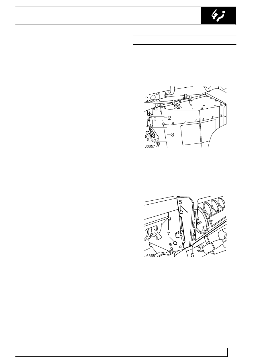
2. From inside engine compartment, release outer
cable retaining clip at heater unit.
3. Slacken trunnion fixing and release inner cable
from heater unit flap lever.
4. Release 2 retaining clips securing control cables
to engine bulkhead and heater hoses.
5. Remove 4 screws securing instrument panel to
fascia cowl.
6. Pull instrument panel away from fascia and
disconnect speedometer cable to ease access to
control cable.
7. Remove 2 screws securing control lever
assembly to side of fascia panel cowl. Note
plastic screw spacers fitted between cowl and
lever assembly and retain.
Parts & tools for this job For Land Rover Defender
- TOOLOBD2 scannerSearch: OBD2 scanner
- TOOLDigital multimeterSearch: automotive digital multimeter
- TOOLBack-probe test leadsSearch: back probe test leads
Links open Amazon search results in a new tab. As an Amazon Associate I earn from qualifying purchases.