
Ignition Timing Compensation
- Make
- Land Rover
- Model
- Freelander Workshop Manual
- Year
- 1998–2000
- Section
- Description and operation › Ignition Timing Compensation
Ignition Timing Compensation
Engine Coolant Temperature (ECT) Sensor
The ECT sensor is located in the coolant outlet elbow which is attached at the front of the cylinder head. The sensor is screwed into a threaded port and measures coolant temperature as it leaves the engine via the top hose to the radiator.
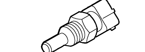
The ECT sensor is a ’thermistor’ (a temperature dependent resistor) with a Negative Temperature Coefficient, i.e. its resistance reduces as temperature increases. The ECM receives a signal from the ECT sensor which is directly proportional to engine coolant temperature. The ECM uses the information to provide optimum driveability and emissions by advancing or retarding the ignition timing.
If the ECT sensor fails, the ECM enters a default mode using a substitute value of 60.2°C, and activates the cooling fan(s) whilst the engine is running.
Idle Speed Control
With the throttle pedal released and the engine at idle, the ECM uses the fast response of ignition timing to maintain idle stabilisation.
When loads are placed on, or removed from the engine the ECM senses the change in engine speed and in conjunction with adjusting the Idle Air Control (IAC) valve, advances or retards the ignition timing to maintain a specified idle speed. When load is removed from the engine, the IAC returns to its original position and the ignition timing returns to the idle setting.
NOTE: Due to the sensitivity of this system the ignition timing will be constantly changing at idle speed.
Ignition Components
Ignition Coil
The coil for the programmed ignition system is mounted on the cylinder head, adjacent to the distributor cap. The coil is connected to the distributor cap centre connection with a short high tension (ht) lead. The use of a ’dry’ ignition coil allows the coil to be mounted on the engine. A two pin plug connects the coil to the engine wiring harness.
The coil has a lower primary winding resistance (0.71 to 0.81 ohms at 20°C) than a coil in a conventional ignition system. This allows the full ht output to be reached faster and so makes the coil operation more consistent throughout the engine speed range. To prevent excessive current draw, and to give a constant energy spark, the ECM constantly varies the ignition coil charge period (dwell period/angle) with engine speed. The faster the engine speed, the larger the dwell period/angle.
If the coil fails, ht output will lost and the engine will stop.
Parts & tools for this job For 1998 Land Rover Freelander
- PARTEngine gasket setSearch: Land Rover Freelander 1998 engine gasket set
- TOOLTorque wrenchSearch: 3/8 inch torque wrench
- TOOLFeeler gauge setSearch: feeler gauge set
Links open Amazon search results in a new tab. As an Amazon Associate I earn from qualifying purchases.