
Fuel Tank and Tank Breather (Fuel delivery system)
- Make
- Land Rover
- Model
- Freelander Workshop Manual
- Year
- 1998–2000
- Section
- Description and operation › Fuel Tank and Tank Breather
Fuel delivery systemFuel Tank and Tank Breather
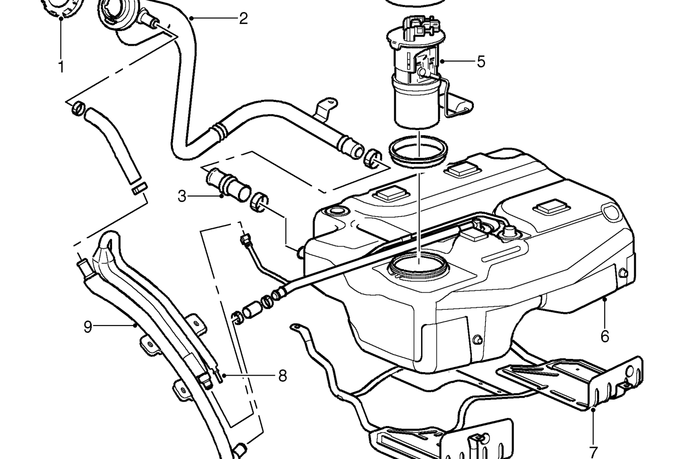
Fuel Tank and Tank Breather
- Filler cap
- Filler tube
- Flexible tube
- Locking ring
- Fuel pick-up and fuel gauge potentiometer
The swirl pot also mixes warm fuel returned from the injection pump with cool fuel in the tank. An access panel below the rear passenger seats provides access to the fuel tank for maintenance.
The fuel tank filler is located on the right hand rear wing panel and is protected by a lockable plastic cap. A plastic tube from the filler is connected to the tank by a flexible rubber tube.
A vent pipe is connected to the neck of the filler to vent fuel vapour during filling of the tank. A smaller vent pipe is also connected to the tank and vents fuel vapour from the tank to atmosphere.
- Fuel tank
- Cradle
- Atmospheric vent
- Vent pipe
Parts & tools for this job For 1998 Land Rover Freelander
- PARTFuel filterSearch: Land Rover Freelander 1998 fuel filter
- TOOLFuel pressure test kitSearch: fuel pressure test kit
- TOOLFuel line disconnect toolSearch: fuel line disconnect tool
Links open Amazon search results in a new tab. As an Amazon Associate I earn from qualifying purchases.