Freelander System Description and Operation

BRAKES
DESCRIPTION AND OPERATION
70-7
Hydraulic System
The hydraulic unit of the modulator consists of a pump, 12 solenoid operated valves and accumulator and damper
chambers. Each brake unit has its own inlet and outlet valves.
The hydraulic system operates the brakes in response to brake pedal movement.
For normal brake operation, brake pedal movement is assisted by the brake servo assembly and transmitted to the
master cylinder assembly. The master cylinder assembly converts brake pedal movement to hydraulic pressure.
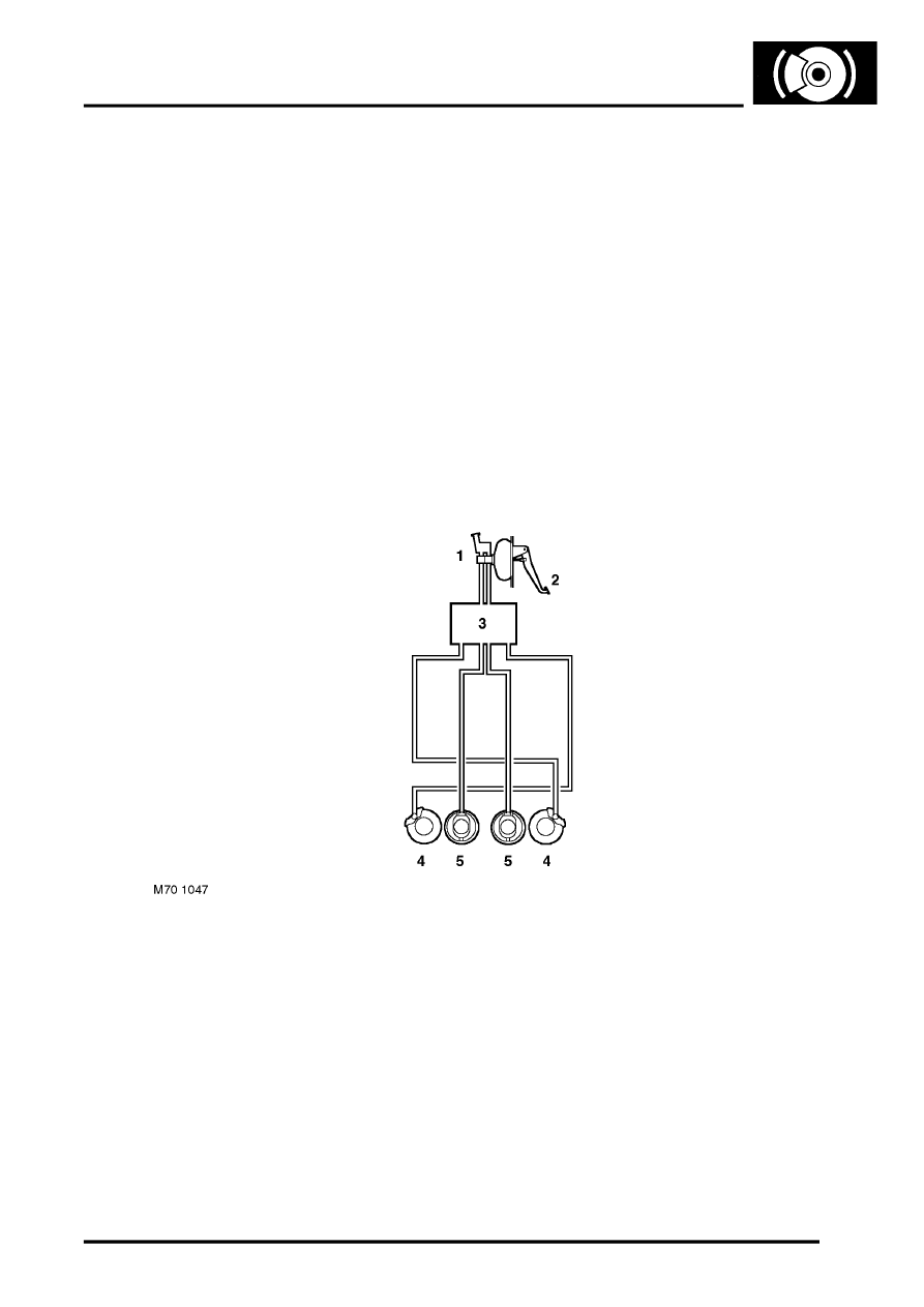
Primary and secondary brake pipe circuits supply the hydraulic pressure to the brakes: the primary circuit supplies
the front left and rear right brakes; the secondary circuit supplies the front right and rear left brakes.
A red, brake warning lamp in the instrument pack illuminates if the fluid level in the hydraulic system falls to an unsafe
level. The brake fluid level is checked via a level switch in the brake fluid reservoir.
On right hand drive vehicles the brake fluid reservoir is remotely located on a bracket on the bulkhead. Left hand drive
vehicles have the brake fluid reserver in the usual position on top of the master cylinder.
Vacuum for the brake servo assembly is obtained from the engine inlet manifold.
To reduce operating noise, sleeving is installed on some of the brake pipes in the engine compartment and the pipes
are located in sprung pipe clips.
ABS Hydraulic System Schematic
1 Servo/Master cylinder assembly
2 Brake pedal
3 ABS modulator
4 Front brake
5 Rear brake
